Binary Logic (UPDATE: 4-Bit CPU simulation, no combincators!)

Circuit-free solutions of basic factory-design to achieve optimal item-throughput.
Involving: Belts (balancers, crossings), Inserters, Chests, Furnaces, Assembling Devices ...
Optimized production chains. Compact design.
Please provide blueprints!
Forum rules
Circuit-free solutions of basic factory-design to achieve optimal item-throughput
zaubara
Burner Inserter
Burner Inserter
Posts: 14
Joined: Fri Jan 02, 2015 11:12 am
Contact:

Binary Logic (UPDATE: 4-Bit CPU simulation, no combincators!)

Post by zaubara »

Hello,

Now that I have my factory running and producing everything in high volume, I decided to experiment with the game mechanics to form binary logic gates and perform math operations.
This is what I came up with:
Image
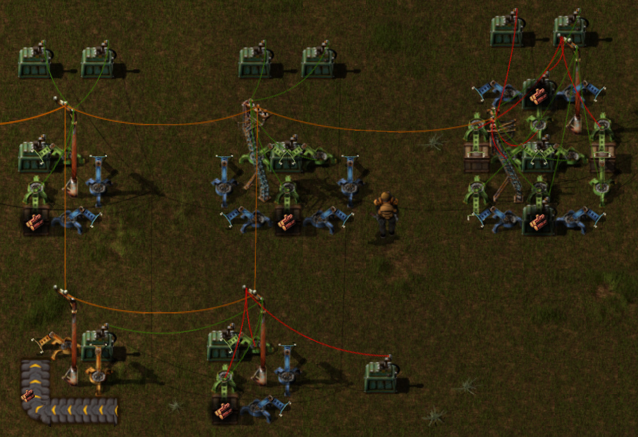
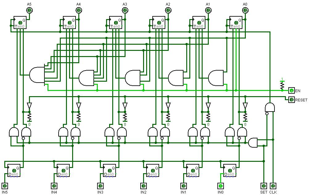
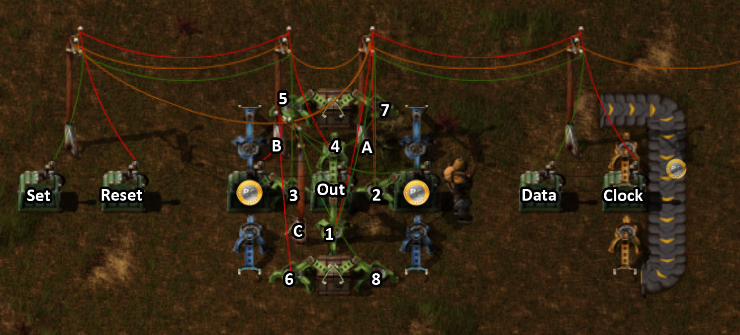
These are my basic cell arrangements to form the binary gates (AND, OR, NOT, XOR, Flip Flops, ...) by adjusting the circuit network wiring/smart inserter rules, which are then used in combination to perform more complex binary operations.
Full album with some description: http://imgur.com/a/tZ2HB#0

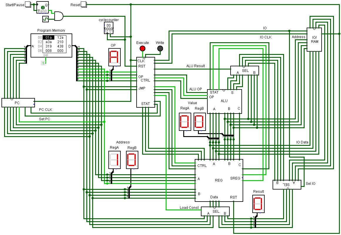
In the album you can already see some bigger arrangements which I want to use to build a simple 4-bit CPU (more a sort of a microcontroller, it will also have the program- and data memories and some peripherals), lets see :)
Last edited by zaubara on Sun Feb 01, 2015 6:14 pm, edited 1 time in total.

Night_Ange1
Long Handed Inserter
Posts: 71
Joined: Wed Dec 03, 2014 1:23 pm
Contact:

Re: Binary Logic

Post by Night_Ange1 »

And so the great computer builds begin! Great work here. Far beyond my knowledge (though probably simple concepts) Congrats and keep up the work :mrgreen:

LordFedora
Filter Inserter
Filter Inserter
Posts: 310
Joined: Fri Nov 07, 2014 3:46 am
Contact:

Re: Binary Logic

Post by LordFedora »

Some work was done previously, albeit he used a mod to make it more compact,

Good work on finding it though, Computer Science is fun (^_^)

https://forums.factorio.com/forum/vie ... gic#p53465

zaubara
Burner Inserter
Burner Inserter
Posts: 14
Joined: Fri Jan 02, 2015 11:12 am
Contact:

Re: Binary Logic

Post by zaubara »

Thank you :)
I did not know that post, seems the forum search function has some flaws... good to see there are more people interested in this topic :)

mikeyjd25
Burner Inserter
Burner Inserter
Posts: 10
Joined: Mon Aug 26, 2013 8:02 pm
Contact:

Re: Binary Logic

Post by mikeyjd25 »

I have been thinking about building a computer in Factorio for a while, maybe now is a good time to start. :)

LordFedora
Filter Inserter
Filter Inserter
Posts: 310
Joined: Fri Nov 07, 2014 3:46 am
Contact:

Re: Binary Logic

Post by LordFedora »

Was actually thinking the same, I'd.need to grab test mode (if anybody has a better suggestion go ahead)

But I want to wait till either 0.11.9 or 0.12

User avatar
-root
Filter Inserter
Filter Inserter
Posts: 651
Joined: Tue Jul 01, 2014 11:24 pm
Contact:

Re: Binary Logic

Post by -root »

This is a bit old hat gentleman.

Youtube - Malkasphia's "Build Codes"
Youtube - A Logic Build by me

That having been said, I'd love to see someone take it to a new level. It's only a matter of time before someone comes along and smashes everything :mrgreen:

Koub
Global Moderator
Global Moderator
Posts: 7175
Joined: Fri May 30, 2014 8:54 am
Contact:

Re: Binary Logic

Post by Koub »

A factory able to run factorio ? :ugeek:
/mind blown, inception style :mrgreen:
Koub - Please consider English is not my native language.

zaubara
Burner Inserter
Burner Inserter
Posts: 14
Joined: Fri Jan 02, 2015 11:12 am
Contact:

Re: Binary Logic

Post by zaubara »

I have prototyped the CPU I am building in Logisim:
Image
It is a 4-Bit CPU with 20 instructions (3 unused), every instruction is 12 bit wide and executed in two cycles, the program memory has a capacity of 64 instructions.
Implemented instructions: ADD, SUB, AND, OR, NOT, XOR, SHL, SHR, JMP, JNZ, JLS, CMP, LDI, MOV, IN and OUT (I've tried to keep it minimalistic)
There are 16 registers available, with R0 as special register which stores the Carry (writeable), Zero and Less (readonly) flags.
Additional RAM and other peripheral IO (memory mapped, inputs/outputs, timer, display, ...) is accessible via IN/OUT.

Because the translation of the assembler code into binary is a tedious process, I've also written a simple Assembler for this CPU:
Image
It shows the binary represantation of the code as well as the hexadecimal, which can be written to a file to load it directly into the program memory in the Logisim simulation. Also supports labels for jump instructions.

Downloads:
4-Bit CPU - contains the Logisim circuit, instruction reference, sample/test programs and the assembler)
4-Bit CPU Assembler Source - Visual Basic .net 2010 source code)

NotABiter
Fast Inserter
Fast Inserter
Posts: 124
Joined: Fri Nov 14, 2014 9:05 am
Contact:

Re: Binary Logic

Post by NotABiter »

So (just looking at the diagram, because reading your text and downloading .zips would be "cheating"):
Top "SEL" is for selecting between 'move' and 'alu' operations.
Middle "SEL" is for selecting between move/alu and "IO/RAM" reads.
Bottom "SEL" is for selecting between move/alu/IO/RAM and bits 8..11 of instruction word (for loading immediates/constants).
IO/RAM writes use register read port A as data and read port B as address.
I don't know why some wires are dark green and some are light green. (I'm not sure it has a meaning. 3 of the wires running to write port A are dark and one is light. Maybe the light/dark is just to make wires easier to follow? It would be cleaner if buses were used.)
I guess the "PC" part has a built in incrementer (enabled by "PC CLK").
"IO" wire controls direction, and "IO CLK" activates IO/RAM feature. (Connections to external IO not shown.)
6 lines between REG and CTRL are for write register, read/write SREG, and to get SREG back to CTRL to implement conditional branches?
With only 6 bits of PC and 4 bits of data address, there can only be 64 words in a program, and 16 nibbles of IO/RAM.

Instruction formats:

two register: 0..3: opcode, 4..7: regA, 8..11: regB
one register with immediate: 0..3: opcode, 4..7: regA, 8..11: immediate value
branches: 0..3: opcode, 4..9: branch target, 10..11: additional opcode bits

There could also be a "one register + additional opcode bits" format, but it would be limited to using instruction word bits 10..11 (because out of instruction word bits 4..11, only 10..11 are connected to CTRL). The fact that those 2 bits are labeled "JMP" would seem to suggest that no "one register + additional opcode bits" instruction format exists.

Anyways, looks sound. Too small for my tastes though. ;)
zaubara wrote:Because the translation of the assembler code into binary is a tedious process, I've also written a simple Assembler for this CPU
What, no LLVM integration? :P

It would be cool if there were some component in the factorio game that allowed simple serial-type communication over some port on 127.0.0.1 so you could easily upload data (programs in this case) into the game from outside of it. I would want to do something bigger (supporting programs significantly larger than 64 instructions), but I don't fancy setting the program memory up bit by bit in-game. I know there's a "blueprint string" importer/exporter plugin - maybe programs can be translated into blueprint strings and then construction robots can be used to program the computer.

zaubara
Burner Inserter
Burner Inserter
Posts: 14
Joined: Fri Jan 02, 2015 11:12 am
Contact:

Re: Binary Logic

Post by zaubara »

NotABiter wrote:So (just looking at the diagram, because reading your text and downloading .zips would be "cheating"):
I won't tell anybody :)
NotABiter wrote:Top "SEL" is for selecting between 'move' and 'alu' operations.
Middle "SEL" is for selecting between move/alu and "IO/RAM" reads.
Bottom "SEL" is for selecting between move/alu/IO/RAM and bits 8..11 of instruction word (for loading immediates/constants).
IO/RAM writes use register read port A as data and read port B as address.
Right, additionally IO/RAM read operations are also handled over RegA/RegB.
NotABiter wrote:I don't know why some wires are dark green and some are light green. (I'm not sure it has a meaning. 3 of the wires running to write port A are dark and one is light. Maybe the light/dark is just to make wires easier to follow? It would be cleaner if buses were used.)
The different coloring indicates the logic state (dark green: 0, light green: 1, blue: undef, red: error). Agree it would look cleaner by using busses, but I like to see the switching when the CPU is running :)
NotABiter wrote:I guess the "PC" part has a built in incrementer (enabled by "PC CLK").
"IO" wire controls direction, and "IO CLK" activates IO/RAM feature. (Connections to external IO not shown.)
Also right, i have not modeled the peripherals in the simulation yet, since they are connected simply to specific memory locations (for example, the digital I/O peripheral would use two memory slots, one for the I/O data and one setting input or output state, these peripheral data is accessible by the CPU with IN/OUT instructions).

Here is the logic diagram of the program counter:
Image

I've also uploaded some more diagrams of the CPU parts (should've done that before, not everybody wants to download the simulator I think...), the album link is in the first post.
NotABiter wrote:6 lines between REG and CTRL are for write register, read/write SREG, and to get SREG back to CTRL to implement conditional branches?
Yes, there is one CLK signal, to write (a part of, ZERO and LS) the SREG each instruction, carry write enable (is only written at specific instructions) and a reg write enable (for standard write operations). Signals going back are, as you said, the SREG (ZERO, LS and EQ, which is unused) for the conditional branching.
NotABiter wrote:With only 6 bits of PC and 4 bits of data address, there can only be 64 words in a program, and 16 nibbles of IO/RAM.
Mainly because of space/CPU load considerations of the Factorio construction, even this small memory needs a lot of inserters (per instruction, 6 cells for the addressing + 12 cells for the data are needed, each cell has 2 smart and 2 fast inserters = 72 inserters per instruction, times 64 = each 2304 smart/fast inserters. That's for the program ROM with not that much logic in it. Plus all the other parts, this is a decent amount of inserters that the game has to manage and I am not quite sure (as mentioned in the other thread) how stable and deterministric this will work. So not to waste all this work ending up with a big but not working processing time consumer, I've rather tried to keep it small and simple. And I think, I've found a good balance of bit widths/instruction size/operations etc.
NotABiter wrote:Instruction formats:

two register: 0..3: opcode, 4..7: regA, 8..11: regB
one register with immediate: 0..3: opcode, 4..7: regA, 8..11: immediate value
branches: 0..3: opcode, 4..9: branch target, 10..11: additional opcode bits

There could also be a "one register + additional opcode bits" format, but it would be limited to using instruction word bits 10..11 (because out of instruction word bits 4..11, only 10..11 are connected to CTRL). The fact that those 2 bits are labeled "JMP" would seem to suggest that no "one register + additional opcode bits" instruction format exists.
Correct. I did not have thought of this additional possible instruction format, that's indeed a way to enhance the command set (some additional ALU operations). I focused just on a minimal instruction set, do you have a suggestion what operations could fit into this?
NotABiter wrote:Anyways, looks sound. Too small for my tastes though. ;)
zaubara wrote:Because the translation of the assembler code into binary is a tedious process, I've also written a simple Assembler for this CPU
What, no LLVM integration? :P
Thanks :) (my Minecraft CPU is much more powerful, but not finished yet :P)
Next weekend, LLVM! The assembler already has JIT-Compile feature ;)
NotABiter wrote:It would be cool if there were some component in the factorio game that allowed simple serial-type communication over some port on 127.0.0.1 so you could easily upload data (programs in this case) into the game from outside of it. I would want to do something bigger (supporting programs significantly larger than 64 instructions), but I don't fancy setting the program memory up bit by bit in-game. I know there's a "blueprint string" importer/exporter plugin - maybe programs can be translated into blueprint strings and then construction robots can be used to program the computer.
That would be awesome. I also thought about a mod for this, but I have no Lua/Modding-experience, maybe here's someone around searching for ideas for a new mod? :)
This could be a sort of smart chest where you can choose the bit position the chest is reading from/writing to, whis has an item in it or not (determining the logic state), plus some control signal chests (Clock, enable, read/write).
As far as I know, it is not possible to set the contents of a chest with blueprint strings, this would also enable such features.

NotABiter
Fast Inserter
Fast Inserter
Posts: 124
Joined: Fri Nov 14, 2014 9:05 am
Contact:

Re: Binary Logic (UPDATE: 4-Bit CPU simulation)

Post by NotABiter »

I probably won't have time to reply to all the stuff I'd like to until next weekend, but I thought I'd get just a few things in quick:

* If you have your constructs in a single game file (e.g., "4 Bit Address, 4 Bit Data RAM"), you might want to consider adding a save game in the first post. It's just really hard to make out what's going on in the pictures with lots of stuff in them. Plus, people can't tweak and play with the pictures. (Though, I don't want to make extra work for you. I was just thinking maybe people could try to optimize your stuff a bit per the next point - such optimization will make more sense though when you start getting some of the "real" parts in.)

* It's (in general) possible to make more efficient computer parts by coding directly in "factorio logic" rather than coding in standard logic cells and then implementing the individual logic cells in factorio. I'm sure you're aware of that already (though maybe not all the tricks), but since you were bringing up how many inserters were required I thought it was worth mentioning. Register file, RAM and program ROM (due to sheer quantity of bits) are the obvious choices for getting as optimized as possible.

EDIT: I don't want to suggest this applies to everyone (or anyone's factorio constructions other than my own), but for me the more important reason for using "factorio logic" directly is fun. I have already played the "standard logic-cell construction game" in many guises, and what makes factorio fresh is getting to build complex things without using standard logic cells. Maximizing speed or minimizing parts/size can provide optimization challenges (aka a "game goal"), but those optimizations of course have no real-world value other than being an excuse to have some fun (and maybe a bit of exercise for the mind).
zaubara wrote:this is a decent amount of inserters that the game has to manage and I am not quite sure (as mentioned in the other thread) how stable and deterministric this will work. So not to waste all this work ending up with a big but not working processing time consumer, I've rather tried to keep it small and simple.
I don't think the number of inserters matters much as long as your PC has enough RAM. Frame rate might drop if your PC doesn't have enough CPU. What does (apparently, maybe) matter is distribution of parts across chunks - but for that my plan is to do some testing first to see exactly what the issues are (and whether or not they can be designed around) rather than try to build a computer in a single chunk. A chunk is only 32x32 tiles (1024 tiles), so even a small computer such as yours is not going to fit in one chunk, so if there really are cross-chunk issues they may impact you.
zaubara wrote:As far as I know, it is not possible to set the contents of a chest with blueprint strings
In this post Ironmarck pointed out that we can make use of blue logistics chests (requester chests). That is, the requester settings of such chests are remembered in blue prints, and whatever requester chests are requesting can be quickly filled using logistics bots. A potential problem with that idea is that bots can overfill requests, but that can be solved by just using a single bot and making sure to not have any logistic bot capacity upgrades. (Maybe there's a better way to solve that, but that's already a zillion times better than driving my character around and trying to set it up manually.) So that takes care of just doing in-game duplication (e.g., hand-make one cell in a register file, then make a blueprint and copy it all over, then use a logistic bot to "initialize" them with the right materials -- feel free to walk away from computer for an hour or ten while it does that).

To import the computer's program you just do the same as above, but instead of making the blueprint in-game you make it outside of the game and import it using a mod such as the Blueprint String mod or Foreman. All that is needed then is an understanding of how blueprint strings are encoded so a proper string (one representing the program "ROM") can be constructed from the program's binary image. (The same technique might also be used to set the initial state of the register file and RAM so you don't have to use up program instructions doing that.)

Utonium
Manual Inserter
Manual Inserter
Posts: 3
Joined: Tue Feb 10, 2015 8:21 am
Contact:

Re: Binary Logic (UPDATE: 4-Bit CPU simulation)

Post by Utonium »

I built a 4-Bit-Adder myself.

http://imgur.com/3Xb7lfW

Currently iam trying to figure out two things:
How to build a Set/Reset D-Flip-Flip with your chest logic.
Is it better to use Chest-Inserter-Logic(CIL) or Inserter-Belt-Logic,
while i thing that your chest logic design is very great and fast, i
saw a belt-inserter logic system on reddit, so i built a simple
multiplexer with this logic family.

http://imgur.com/0psA9Ma

Why do you use chest-inserter logic
instead of inserter belt logic? Good luck with your CPU project
iam trying set one up myself. ^^

zaubara
Burner Inserter
Burner Inserter
Posts: 14
Joined: Fri Jan 02, 2015 11:12 am
Contact:

Re: Binary Logic (UPDATE: 4-Bit CPU simulation)

Post by zaubara »

NotABiter wrote:* If you have your constructs in a single game file (e.g., "4 Bit Address, 4 Bit Data RAM"), you might want to consider adding a save game in the first post. It's just really hard to make out what's going on in the pictures with lots of stuff in them. Plus, people can't tweak and play with the pictures. (Though, I don't want to make extra work for you. I was just thinking maybe people could try to optimize your stuff a bit per the next point - such optimization will make more sense though when you start getting some of the "real" parts in.)
My plan is of course to add a map download with the construction in it! At the moment, I am building the parts for itself, make a blueprint and deconstruct it them, to keep the FPS up during building and to know the outlines when finally arranging them. There is also a factory running to supply the materials and to possibly have something to interact with when the CPU is able to execute programs.
NotABiter wrote:* It's (in general) possible to make more efficient computer parts by coding directly in "factorio logic" rather than coding in standard logic cells and then implementing the individual logic cells in factorio. I'm sure you're aware of that already (though maybe not all the tricks), but since you were bringing up how many inserters were required I thought it was worth mentioning. Register file, RAM and program ROM (due to sheer quantity of bits) are the obvious choices for getting as optimized as possible.
I am sure there are many possible optimizations in these designs, I try to have a compromise between strict logic builds with individual cells following exactly the definition and heavily optimized constructions for a particular purpose (for example, I only use a single item type to code bits, although some things could be done more efficient by using different items for bits in one network, but it helps me to maintain the overview). Same applies to the program memory, you could leave out the cells coding a 0, which is also my prefered way to import memory contents by blueprints/bots (maybe i'll code an blueprint export feature into the assembler later). The only thing that bothers me a bit with this method (using a blue chest to request the bit items) is the need not to have bot capacity upgrades, hopefully the behaviour is adjusted that they just carry the exact amount of requested items. So my intent coding the first test programs in the memory is to simply put an item per hand into the ROM array for each 1.
Do you have some tricks or other interesting solutions you want to share?
NotABiter wrote:
zaubara wrote:this is a decent amount of inserters that the game has to manage and I am not quite sure (as mentioned in the other thread) how stable and deterministric this will work. So not to waste all this work ending up with a big but not working processing time consumer, I've rather tried to keep it small and simple.
I don't think the number of inserters matters much as long as your PC has enough RAM. Frame rate might drop if your PC doesn't have enough CPU. What does (apparently, maybe) matter is distribution of parts across chunks - but for that my plan is to do some testing first to see exactly what the issues are (and whether or not they can be designed around) rather than try to build a computer in a single chunk. A chunk is only 32x32 tiles (1024 tiles), so even a small computer such as yours is not going to fit in one chunk, so if there really are cross-chunk issues they may impact you.
It definitely won't fit into a single chunk. I also don't think it will work tick-exact, but by extending the clock the CPU should still work without problems.
Utonium wrote:I built a 4-Bit-Adder myself.
http://imgur.com/3Xb7lfW
Looks clean and nice! You start with the LSB on the left side?
Utonium wrote:Currently iam trying to figure out two things:
How to build a Set/Reset D-Flip-Flip with your chest logic.
A possible solution (I have also switched the bit item, coins have a more distinct appearance): Image
The output could be set by a clocked data input or by separate, asynchronous set/reset inputs.
Setup:
Pole A: Data (green), Clock (red)
Pole B: Set (green), reset (red)
Pole C: Left bit storage (green), right bit storage (red)
Inserter 1: Pole A, R > 0, G > 0
Inserter 2: Pole A, R > 0, G < 1
Inserter 3: Pole B, G > 0
Inserter 4: Pole B, R > 0
Inserter 5, 6: Pole C, R < 1
Inserter 7, 8: Pole C, G < 1
Utonium wrote:Is it better to use Chest-Inserter-Logic(CIL) or Inserter-Belt-Logic,
while i thing that your chest logic design is very great and fast, i
saw a belt-inserter logic system on reddit, so i built a simple
multiplexer with this logic family.

http://imgur.com/0psA9Ma

Why do you use chest-inserter logic
instead of inserter belt logic? Good luck with your CPU project
iam trying set one up myself. ^^
I think both solutions are more or less exchangeable, but I prefer to use the belt layout for clocks, because you have more control over the timings and the inserter layout for everything else, because there is also room to fit some poles in it and you can control if inserters take item per item or all items in the chest at once by placing a receiving chest (with inserter capacity upgrades), as I have used in the D-FF design above.
Thanks and same to you :) Keep posting about your progress!

NotABiter
Fast Inserter
Fast Inserter
Posts: 124
Joined: Fri Nov 14, 2014 9:05 am
Contact:

Re: Binary Logic (UPDATE: 4-Bit CPU simulation)

Post by NotABiter »

zaubara, I tried to look at your 4-Bit-CPU.zip file. It downloads as a 67,466 byte file, but when I try to unzip it:
C:\temp\factorio>unzip 4-Bit-CPU.zip
Archive: 4-Bit-CPU.zip
End-of-central-directory signature not found. Either this file is not
a zipfile, or it constitutes one disk of a multi-part archive. In the
latter case the central directory and zipfile comment will be found on
the last disk(s) of this archive.
unzip: cannot find zipfile directory in 4-Bit-CPU.zip,
and cannot find 4-Bit-CPU.zip.zip, period.
I tried InfoZip (above), windows explorer and 7-Zip and they all say the zip file is invalid.
zaubara wrote:do you have a suggestion what operations could fit into this?
Well, you asked for it. :twisted:

Since I can't look at the details in 4-Bit-CPU.zip, I'm just going by the instruction list you gave earlier:
zaubara wrote:ADD, SUB, AND, OR, NOT, XOR, SHL, SHR, JMP, JNZ, JLS, CMP, LDI, MOV, IN and OUT
If NOT, SHL, SHR use the same register as both source and destination (as is common in most actual machine languages), then those instructions would be candidates for the one-register format.

I don't think your current datapath supports it, but I see you have LDI and MOV as separate instructions, and don't have ADDI, SUBI, ANDI, ORI, XORI or CMPI. Considering how much instruction space you have available it would make sense to generalize ADD, SUB, AND, OR, XOR, CMP and LDI/MOV to be able to have the second source operand be either a register or an immediate, and then LDI is just the 'I' variant of MOV. Just use one of the opcode bits to select between use-immediate and read-reg-B. That would also allow coding "ADDI r, 1" and "SUBI r, 1" in a single instruction, which would eliminate any need for one set of commonly included single-register instructions: INC, DEC

Argh - I just tried it and having 'I' variants of everything almost fits, but not quite. I think it would be worth considering expanding the instruction size from 12 bits to 13 bits because even though that's an 8% increase in instruction size, it would likely decrease a program's size by more than 8%. Here's my attempt at fitting into 12 bits:

Code: Select all

xxx0 (xxx != 0): two register; xxx1 (xxx != 0): one register + one immediate
0010 ADD   0011 ADDI
0100 SUB   0101 SUBI
0110 AND   0111 ANDI
1000  OR   1001  ORI
1010 XOR   1011 XORI
1100 CMP   1101 CMPI
1110 MOV   1111 MOVI

load/store (IN/OUT):
0000 IN    1000 OUT

sorry, no opcode space left for:
NOT, SHL, SHR
JMP, JNZ, JLS
With 13 bits there's plenty of space (even with 'I' variants of IN/OUT as well so you can read/write absolute IO/RAM addresses without having to preload the address in a register):

Code: Select all

xxxx0 (xxxx <= 1000): two register; xxxx1 (xxxx <= 1000): one register + one immediate
00000  IN   00001  INI
00010 OUT   00011 OUTI
00100 ADD   00101 ADDI
00110 SUB   00111 SUBI
01000 CMP   01001 CMPI
01010 AND   01011 ANDI
01100  OR   01101  ORI
01110 XOR   01111 XORI
10000 MOV   10001 MOVI

10010 unused/available
...
11101 unused/available

11110 one-register instructions (NOT, SHL, SHR; up to 4 additional opcode bits used for operation type)
11111 branches (JMP, JNZ, JLS; 2 additional opcode bits used for branch type)
If I were creating a real instruction set (especially a 4-bit one!), there's some more instructions that would be needed for practical use ("practical use" in factorio definitely including the ability to add, subtract, compare and shift values greater than 4 bits):

Code: Select all

10100 ADDC  10101 ADDCI (add with carry)
10110 SUBC  10111 SUBCI (subtract with carry/borrow)
11000 CMPC  11001 CMPCI (compare with carry/Z-flag; see CPC instruction in Atmel AVR instruction set if you've never seen something like this - a lot of architectures have a big gaping whole where this instruction belongs!)
one-register instructions: ROR, ROL (rotate right/left though carry)
The move to 13 bits would also let you have a full set of conditional branches rather than just JNZ/JLS. (That can also save program space by not needing to use the "conditional branch around unconditional branch" idiom to synthesize the branch you really want.)

It's also common to have an ASR (arithmetic shift right) instruction for shifting signed data. (I'm assuming your current SHR instruction shifts 0s in rather than duplicating the sign bit.)

A lot of instruction sets also have some way to read/write flags registers (to/from a register and/or to/from memory). For most code, though, that's probably more "nice to have" than "essential".

One big thing that's really missing from your instruction set is an ability to do proper subroutines. Currently you could use one register as a stack pointer, and by manipulating it with ADD/SUB and using it as an address you could push and pop data. You could even store a return address (as two nibbles) by doing two 'LDI's with the two parts of the return address and then using 'OUT's to push them to the stack. You could also pop the return address into two registers. So far, so good (if a bit verbose in terms of instruction words used). But then there's one last missing piece to pull it off, and that is that you don't have an indexed jump instruction (i.e., an instruction that does "jump to address stored in register(s)"). So even with the return address sitting in two registers (two because addresses are 6 bits and registers are only 4 bits), there's no way to jump back to the return address. (Adding that feature would also fix the lack of ability to do jump tables, though your program size is so small jump tables are probably something you'd never use anyways, so really it's making subroutines work that is the issue here.)

In super-small architectures (with very little program memory), subroutines are your friend. (Some might say they are your Lord and Savior Jesus Christ because they're that important to getting programs to fit.) There is a work-around, but it's a bit ugly. And that is to have every subroutine know about all of its callers. Then for each subroutine enumerate the callers 0..N-1. Instead of pushing/popping an address you push/pop that index. Then instead of doing a normal kind of return-from-subroutine, you end each subroutine with a bunch of CMPs (comparing the popped index) alternating with conditional branches to the (hard-coded) return addresses. (You could teach this idiom to your assembler and have it do this automagically -- then have JSR and RET pseudo-instructions.) Of course, between this and not having proper PUSH/POP instructions, your overhead (not just in timing but in amount of program space consumed) for subroutines and subroutine calls is going to be pretty high. (Personally I am somewhat fond of the 6809 instruction set where a 2-byte POP instruction can pop any arbitrary combination of Flags, A, B, X, Y, and U registers, as well as the PC so you don't even need a separate RETurn instruction.)

If this were a real instruction set I would also complain loudly about the lack of any register+immediate_offset addressing. But I can understand that that would be quite a bit of work to add in this case because it requires 2 registers and an offset which would mean it would have to be a multi-program-word instruction which would really complicate your instruction decoding and control scheme. If, kind of like how I believe the MIPS assembler works, you dedicate one register as "assembler-owned/controlled temporary register", you could make your assembler emulate the addressing mode, though it will take 3 instruction words instead of just 2: MOV reg to temp, ADD offset to temp, then do the IN/OUT instruction using temp as the address

Push/pop instructions are also really good candidates for being assembler pseudo instructions. Just have one register that is considered "the stack pointer". Then the assembler accepts instructions like "push r1, r7, r10" and outputs machine code: subi sp, 1; out sp, r1; subi sp, 1; out sp, r7; subi sp, 1; out sp, r10

Auto-increment/auto-decrement addressing is another good candidate for being pseudo instructions -- the assembler accepts "out r8++, r4; out r8++, r5" and outputs "out r8, r4; addi r8, 1; out r8, r5; addi r8, 1"

Of course, you can get carried away with that. I mean, once you start introducing math operations with absolute memory addressing as a pseudo-instruction (e.g., assembler accepts "add foo, 1" and outputs "ini temp, addressof(foo); addi temp, 1; outi addressof(foo), temp") you've almost got a C compiler -- may as well make it just accept "foo++" as a statement. :P

Motorola had an interesting concept which I don't know if you're interested in, but since you create different CPUs maybe you are... the concept was basically "(somewhat) portable assembly language". They used this in the 68xx line of microprocessors and microcontrollers. At a machine code level, they had different instruction sets and encodings (some much more capable than others), but (in theory, I didn't try this myself, even though I have both 6809 and 6811 experience - also 6803 but I only programmed that in machine code, never had an assembler) you could write assembly code that worked on all of them. On "lesser architectures" that assembly code would translate to a lot more machine instructions, but it would still work.
zaubara wrote:"6 cells for the addressing"
zaubara wrote:Do you have some tricks or other interesting solutions you want to share?
Have? Yes. Want to share... um, er, I guess. :?

(If I give away my secrets, how will I build the super-duperest 'puter?)

For example, it doesn't take 6 cells to do addressing. As long as you have the inserter stack bonuses, you can move up to 5 items at a time. You can do some extra work up-front on the address before "transmitting" it up to the address decoders - have one cell moving 4 items, one moving 2 and one moving 1. (Obviously anything greater than 1 can't involve belts, and the obvious choice is box-to-box.) You can then "wire-add" those together (just tie them together with a single red/green wire and let factorio add up the item counts: 0..7). That lets you code 3 bits into one wire. But you need 6 bits? Fine, do it twice, use two different materials, and now you can put 6 bits into one wire. At each program word just use 2 cells, one for each group of 3 bits. (Just set the logic condition to be "wood=0" .. "wood=7" to decode the first 3 bits in the first cell, and "iron_ore=0"..."iron_ore=7" for the other 3 bits in the second cell.) Have I blown your mind yet? No? Then how about doing it in one cell. One cell requires using both red and green wires (3 bits each), and then you can set both conditions on the one cell. But where's the clock coming from then? Logistics network! :ugeek:

The above trick can also be used when MUXing different result buses together.

You can do a similar thing with the program words themselves, storing 2 bits per cell. When moving items into "read position", move up to 3 items at once. (Unfortunately I haven't figured out how to do a similar trick with RAM yet. This trick might not be much of a win if you have enough '0' bits you could have just left out anyways.)

(OK, I really need to test these ideas. Maybe I'm just full of crap. I started a new game with 11.15 with resources all set to high and biters set to low because I think that would be a good environment for building a really big computer, but I still haven't got to the computer building/testing part yet -- this game takes too many damn hours!)

***

Anyone working on a computer based on 0.11.x may want to hurry up, as 0.12 may make it "obsolete". (It might still work, but would not be very good compared to what can be made in 0.12 -- but then again, that may be a good excuse to make another computer!) From here:
To be able to manipulate the signal better, we will have a new piece called combinator. This piece will allow to do certain manipulations with the signal, like conditional statements or multiplications (simple linear combinations).
Also, from that same post is news that 0.12 will have 'stdout' covered:
light, condition can be specified, can be colored depending the singal
EDIT: zaubara, if you have the XORI instruction, then you don't need the NOT instruction -- you can just do "XORI reg, 0x0f" rather than "NOT reg".

zaubara
Burner Inserter
Burner Inserter
Posts: 14
Joined: Fri Jan 02, 2015 11:12 am
Contact:

Re: Binary Logic (UPDATE: 4-Bit CPU simulation)

Post by zaubara »

NotABiter wrote:zaubara, I tried to look at your 4-Bit-CPU.zip file. It downloads as a 67,466 byte file, but when I try to unzip it:
C:\temp\factorio>unzip 4-Bit-CPU.zip
Archive: 4-Bit-CPU.zip
End-of-central-directory signature not found. Either this file is not
a zipfile, or it constitutes one disk of a multi-part archive. In the
latter case the central directory and zipfile comment will be found on
the last disk(s) of this archive.
unzip: cannot find zipfile directory in 4-Bit-CPU.zip,
and cannot find 4-Bit-CPU.zip.zip, period.
I tried InfoZip (above), windows explorer and 7-Zip and they all say the zip file is invalid.
I could confirm that, I have replaced the zip file, it should work now (tested with 7-zip x64). I used the explorer zip function, Win7 X64, and have updated a file in the archive later, don't know what caused the corruption...

I very like your suggestions for the command set, I think it is well worth adding a 13th bit to the instruction size! While laying out the instruction set, I also thought about immediate variants, but I discarded because 12 bits were not sufficient as you've shown. An additional bit will not consume very much space but the instructions you can save speed up the execution of the program.
NotABiter wrote:If I were creating a real instruction set (especially a 4-bit one!), there's some more instructions that would be needed for practical use ("practical use" in factorio definitely including the ability to add, subtract, compare and shift values greater than 4 bits):

Code: Select all

10100 ADDC  10101 ADDCI (add with carry)
10110 SUBC  10111 SUBCI (subtract with carry/borrow)
11000 CMPC  11001 CMPCI (compare with carry/Z-flag; see CPC instruction in Atmel AVR instruction set if you've never seen something like this - a lot of architectures have a big gaping whole where this instruction belongs!)
one-register instructions: ROR, ROL (rotate right/left though carry)
Sorry you couldn't have a look at the simulation yet, all these instructions (ADD, SUB, SHL, SHR) are already the carry-variants, calculacting with the C-bit from the SREG and then writing the resulting C into SREG. The C bit can be set by any reg write instruction on Reg0 (only C bit 0 is writeable).
NotABiter wrote:It's also common to have an ASR (arithmetic shift right) instruction for shifting signed data. (I'm assuming your current SHR instruction shifts 0s in rather than duplicating the sign bit.)
Agree it is a good thing to add, should be possible with the 13th bit.
NotABiter wrote:One big thing that's really missing from your instruction set is an ability to do proper subroutines. Currently you could use one register as a stack pointer, and by manipulating it with ADD/SUB and using it as an address you could push and pop data. You could even store a return address (as two nibbles) by doing two 'LDI's with the two parts of the return address and then using 'OUT's to push them to the stack. You could also pop the return address into two registers. So far, so good (if a bit verbose in terms of instruction words used). But then there's one last missing piece to pull it off, and that is that you don't have an indexed jump instruction (i.e., an instruction that does "jump to address stored in register(s)"). So even with the return address sitting in two registers (two because addresses are 6 bits and registers are only 4 bits), there's no way to jump back to the return address. (Adding that feature would also fix the lack of ability to do jump tables, though your program size is so small jump tables are probably something you'd never use anyways, so really it's making subroutines work that is the issue here.)

In super-small architectures (with very little program memory), subroutines are your friend. (Some might say they are your Lord and Savior Jesus Christ because they're that important to getting programs to fit.) There is a work-around, but it's a bit ugly. And that is to have every subroutine know about all of its callers. Then for each subroutine enumerate the callers 0..N-1. Instead of pushing/popping an address you push/pop that index. Then instead of doing a normal kind of return-from-subroutine, you end each subroutine with a bunch of CMPs (comparing the popped index) alternating with conditional branches to the (hard-coded) return addresses. (You could teach this idiom to your assembler and have it do this automagically -- then have JSR and RET pseudo-instructions.) Of course, between this and not having proper PUSH/POP instructions, your overhead (not just in timing but in amount of program space consumed) for subroutines and subroutine calls is going to be pretty high. (Personally I am somewhat fond of the 6809 instruction set where a 2-byte POP instruction can pop any arbitrary combination of Flags, A, B, X, Y, and U registers, as well as the PC so you don't even need a separate RETurn instruction.)

Push/pop instructions are also really good candidates for being assembler pseudo instructions. Just have one register that is considered "the stack pointer". Then the assembler accepts instructions like "push r1, r7, r10" and outputs machine code: subi sp, 1; out sp, r1; subi sp, 1; out sp, r7; subi sp, 1; out sp, r10
Yes it really lacks the ability for proper sub-routines. That's one of the first things I've wanted to add when I have the CPU running, but now I am considering to include this in the first iteration, since there is more instruction space available. I could use the 13th bit as Jump-op, adding 4 more jump instructions. I favour having the stack operations done in hardware, the emulation is a instruction-consuming task which could make the subroutine obsolete. Maybe I'll add a special instruction type with more cycles to write the two nibbles, I'll have to think a bit about it...
Additionally the .org directive could be added to the assembler, to have common sub routines located at the end of the memory for example.
NotABiter wrote:If this were a real instruction set I would also complain loudly about the lack of any register+immediate_offset addressing. But I can understand that that would be quite a bit of work to add in this case because it requires 2 registers and an offset which would mean it would have to be a multi-program-word instruction which would really complicate your instruction decoding and control scheme. If, kind of like how I believe the MIPS assembler works, you dedicate one register as "assembler-owned/controlled temporary register", you could make your assembler emulate the addressing mode, though it will take 3 instruction words instead of just 2: MOV reg to temp, ADD offset to temp, then do the IN/OUT instruction using temp as the address.
Hmm, that could also be achieved by a separate adder + demux in hardware, does not take up very much space, only 2 operands needed... But I'd rather leave this for later designs :)
NotABiter wrote:Auto-increment/auto-decrement addressing is another good candidate for being pseudo instructions -- the assembler accepts "out r8++, r4; out r8++, r5" and outputs "out r8, r4; addi r8, 1; out r8, r5; addi r8, 1"

Of course, you can get carried away with that. I mean, once you start introducing math operations with absolute memory addressing as a pseudo-instruction (e.g., assembler accepts "add foo, 1" and outputs "ini temp, addressof(foo); addi temp, 1; outi addressof(foo), temp") you've almost got a C compiler -- may as well make it just accept "foo++" as a statement. :P
This is the path to the dark side ;) The assembler performs a second pass, adding macros is not complicated...
NotABiter wrote:Motorola had an interesting concept which I don't know if you're interested in, but since you create different CPUs maybe you are... the concept was basically "(somewhat) portable assembly language". They used this in the 68xx line of microprocessors and microcontrollers. At a machine code level, they had different instruction sets and encodings (some much more capable than others), but (in theory, I didn't try this myself, even though I have both 6809 and 6811 experience - also 6803 but I only programmed that in machine code, never had an assembler) you could write assembly code that worked on all of them. On "lesser architectures" that assembly code would translate to a lot more machine instructions, but it would still work.
Didn't know that, sounds interesting! They achieved this with different instruction sizes (16, 32 bit-instructions)? I only know the AVR architecture quite well, doing also assembler code for it from time to time, and a bit of MSP430x.
NotABiter wrote:For example, it doesn't take 6 cells to do addressing. As long as you have the inserter stack bonuses, you can move up to 5 items at a time. You can do some extra work up-front on the address before "transmitting" it up to the address decoders - have one cell moving 4 items, one moving 2 and one moving 1. (Obviously anything greater than 1 can't involve belts, and the obvious choice is box-to-box.) You can then "wire-add" those together (just tie them together with a single red/green wire and let factorio add up the item counts: 0..7). That lets you code 3 bits into one wire. But you need 6 bits? Fine, do it twice, use two different materials, and now you can put 6 bits into one wire. At each program word just use 2 cells, one for each group of 3 bits. (Just set the logic condition to be "wood=0" .. "wood=7" to decode the first 3 bits in the first cell, and "iron_ore=0"..."iron_ore=7" for the other 3 bits in the second cell.) Have I blown your mind yet? No? Then how about doing it in one cell. One cell requires using both red and green wires (3 bits each), and then you can set both conditions on the one cell. But where's the clock coming from then? Logistics network! :ugeek:

The above trick can also be used when MUXing different result buses together.

You can do a similar thing with the program words themselves, storing 2 bits per cell. When moving items into "read position", move up to 3 items at once. (Unfortunately I haven't figured out how to do a similar trick with RAM yet. This trick might not be much of a win if you have enough '0' bits you could have just left out anyways.)
Ok I think I understand, a very gate-saving method. But for decoders, having distinct gates per bit in each coded row has also its advantages, you always have just a single gate delay. Good trick with the logistic network, I'll have to try this :)
NotABiter wrote:(OK, I really need to test these ideas. Maybe I'm just full of crap. I started a new game with 11.15 with resources all set to high and biters set to low because I think that would be a good environment for building a really big computer, but I still haven't got to the computer building/testing part yet -- this game takes too many damn hours!)
Same here :) The factory distracts the attention all the time. I also don't know if I should just continue building or wait for the 0.12 to make everything before obsolete :)

NotABiter
Fast Inserter
Fast Inserter
Posts: 124
Joined: Fri Nov 14, 2014 9:05 am
Contact:

Re: Binary Logic (UPDATE: 4-Bit CPU simulation)

Post by NotABiter »

Ugly! Ugly bags of water!

(ST:TOG reference - it's kind of how I see my proposal now... using binary instruction words for a factorio computer is just ugly! Outside of factorio it's kind of cute, but not inside because...)

I've figured out two different ways to do this at least 4 times better, as in: Instead of 12 or 13 cells per instruction word it's just 3 or 4 cells. And it's even better than that because it also allows all kinds of flexibility in the instructions (e.g., optional fields, variable size fields) with zero cost. One of the ways also seems to allow the program to be expressed in a remarkably meaningful way inside the game - making both data flow and control flow explicitly represented visually in the game, though I'm still working out some details on that version. (It could already be made to work in its current state, but I think I still have improvements left to make. Funnily enough, it's how subroutines should work that I'm still working on.)
zaubara wrote:all these instructions (ADD, SUB, SHL, SHR) are already the carry-variants, calculacting with the C-bit from the SREG and then writing the resulting C into SREG. The C bit can be set by any reg write instruction on Reg0 (only C bit 0 is writeable).
You're missing one in your list there (the compare). Also to be "proper" you should handle the Z flag as well. Basically if you do something like a 16 bit addition/subtraction/compare using 4 4-bit adds/subtracts/compares, the flags should end up (and subsequent conditional branches should work) exactly the same as if you had native support for 16 bit math operations. E.g., "JZ" should actually work properly after a (synthesized) 16-bit operation, and not just jump based on whether the last 4 bits were zero. Anything else is just clunky - admittedly a lot of real machines are clunky but I don't consider that an excuse. :P (I have to actually sit down and work the details of this out myself for my own factorio computer, but I've been putting it off until I know what my data size is going to be. If I go with a native data size of 32 bits or more I might just skip support for extended length math operations.)
zaubara wrote:Yes it really lacks the ability for proper sub-routines.
I wish I could make subroutines work as crazy efficiently as this. I was looking at that video because I had never heard of a "belt architecture" before (as opposed to a register or stack architecture), and what could be more thematically appropriate for a factorio computer then a belt architecture? Their subroutine support is incredibly good. They describe their function call instruction @28:24 into the video -- a single instruction not only calls the function but passes all of the (belt-based) parameters as well. (Because of the way the belt architecture works there's no need to save/restore registers, so passing parameters in and making the call is all that's needed.) And they have built-in hardware support for multiple return values. Inputs/outputs to user functions behave exactly the same as for native instructions. And as mentioned @ 54:00, you can pass/return an entire belt full of arguments, and call/return are still single cycle operations. (Their whole architecture is quite impressive. They seem to have really thought out and brought a number of very effective solutions to the architectural problems that are choking other high-ILP processor designs. If you're into processor architecture you might want to watch the whole video and some of the others -- this machine literally executes instructions forwards and backwards at the same time - using two PCs, because that results in fundamentally faster instruction decode. Crazy stuff.)
zaubara wrote:I favour having the stack operations done in hardware
Sounds good to me. (I only suggested pseudo-instructions because I didn't want to "push" too many changes on you. Oh my, excuse my pun. :oops: )
zaubara wrote:Additionally the .org directive could be added to the assembler, to have common sub routines located at the end of the memory for example.
I've got no idea what you mean by that, unless it's that you want to fix the address of the subroutines so you can change the non-subroutine code without having the subroutines get shifted around?
zaubara wrote:They achieved this with different instruction sizes (16, 32 bit-instructions)?
Instruction encoding size doesn't matter, because you reassemble the same assembly source for the given MCU - the assembler will take care of making branches go to the right new place. If you meant different data sizes, then yes, it did handle that. E.g., the architecture defined the D register as a 16 bit register that consists of two 8 bit registers, the A and B registers. In assembly you could do "ADDD #$1234" to add a 16-bit immediate to the D register, and on the 6809 that was a native 3-byte instruction (though I would not be surprised if that was handled in microcode as two 8 bit adds). For the 6800 I believe the assembler would spit out "ADDB #$34; ADCA #$12", emulating the 16 bit operation with two 8 bit operations (2 2-byte instructions). Another case I know about is the multiplier - 6809 has an 8 bit hardware multiplier, 6800 not so much, but MUL instruction works on both - for the 6800 when the assembler sees a MUL instruction it emits a call to a multiply subroutine (which it provides as needed) whereas for the 6809 the assembler emits a 1-byte MUL instruction. (SPARC does some similar stuff these days, though at runtime rather than assembly time, because some of the instructions they used to implement in hardware are no more - with modern SPARC chips such instructions get caught by the invalid instruction trap, and then emulated. It's sad because those instructions were meant for maximum speed - IIRC bitscan is one of the instructions that got nixed - and now they are massively slow.)
zaubara wrote:But for decoders, having distinct gates per bit in each coded row has also its advantages, you always have just a single gate delay.
That (it being an advantage) is not necessarily true. Because the pre-conditioning I was talking about could be made a built-in (zero latency cost) part of the previous logic bits (or parallel to them if wiring their outputs together is an issue), though obviously some of those bits would have to use boxes to implement their logic instead of belts. (There's no "gates-per bit" in either of my two new schemes, and there's no known unnecessary latency either.)

Let's see if you can figure out how to crush instruction "words" down to just a few cells each (with no loss of features) before I get around to doing some kind of write-up. (Who knows, I've already found two ways to do it, maybe you'll find a third way.)

This section is bogus:
EDIT: I just came up with a 3rd way of doing it - this time in only 2 cells, and unlike my other two ideas this one is compatible with a bit-encoded instruction set. Since (unlike my other schemes) it could be compatible with the rest of your current design, I'll quickly describe it now: Each cell consists of 4 boxes placed in the corners of a 3x3 tile square. Smart inserters connect all boxes together in a clock-wise fashion. Call the lower-left and top-right boxes the "active boxes" and the other two boxes the "inactive boxes". The active boxes have to be smart chests and are wired together and are wired to a "read data" line. Use up to one each of 10 different materials. Each material type represents a different bit, so 10+ bits are represented. ("10+" rather than just "10" because only one bits need to be included. 2 cells supports 20+ bits, so you could extend your instruction set from 13 bits to 20 bits "for free" if you like.) Place at most 5 of the items in each inactive box. When the address decoders trigger, the two smart inserters feeding the active boxes are enabled -- all bits are moved from inactive boxes to active boxes in a single arm movement. When a global signal triggers (what this signal is called depends on your architecture/design, but in this context it means "end program read"), the two smart inserters feeding the inactive boxes are enabled -- all bits are moved from active boxes to inactive boxes in a single arm movement.

BONUS #1: Remember the single-cell address decoder I mentioned previously? It can be adapted here to be a zero-cell address decoder. That is, you can use the 3 inputs (3 bits red + 3 bits green + logistics clock) and tie them directly to the smart inserters feeding the active boxes. So it's just two cells (4 smart chests, 4 dumb chests, 8 smart inserters) per 20+ bit program word, total.

BONUS #2: You can effectively/reliably get more than 20 bits of data in each program word by using more than 20 different material types -- even while sticking to at most 20 pieces of material in the 2 cells. (I'll explain this in more detail later if you can't figure it out on your own. It might even be possible to squeeze your original instruction set down to a single cell this way, but I'd have to think about it some more to know if that's really possible. At least I'm pretty confident in saying that it's not possible to get it down to 0 cells per program word, so I think it's pretty close to optimal. :D )

BONUS #2a: I figured out right after I posted BONUS #2 that the most regular/general way to get more bits (there are I believe a multitude of ad hoc ways to do it) is this: For each additional bit you want, add 2 more types of material. Change one of your (10 per cell) "cell slots" to use 3 different materials (still only qty one in any given cell) instead of 1 material. That allows that cell slot to encode 2 bits instead of just 1 (but also impacts instruction decoding, for better or for worse). So for your current instruction set you can encode 12 bits in 1 cell using 14 materials, or 13 bits in 1 cell using 16 materials.

EDIT #2: Fixed "Place at most 5 of the items in each active box" in original EDIT to be "Place at most 5 of the items in each inactive box"


Ugh, somehow I managed to forget that an inserter can't move items of different types at the same time. That limitation wrecks the 3rd way above (all the greyed-out text, select the text if you want to read how stupid I was - though the idea in "BONUS #1" is still valid and can be applied to the 1st way I came up with, and in fact can be extended to more bits and to not need to use the logistics network). The limitation doesn't completely wreck the 1st and 2nd ways I came up with, as they don't require sticking more than one material type in a box (though even for them I was thinking there would be potential optimizations in some cases -- now those optimizations are limited to sticking different materials in the same cell but not in the same box, which means at most two material types per cell). I will try to document those two ways this weekend (if not sooner) -- I want to actually make them and test them in the game and then put them in my own computer thread.

A replacement/fixed "3rd way" is to always use exactly two material types per cell. Place 0..3 items of one material type in one inactive box, and 0..3 items of a second material type in the other inactive box. That lets you put 2 bits in each inactive box, for a total of 4 bits per cell. That scheme (unlike the 1st/2nd ways) is compatible with a bit-encoded program-word design such as yours. For 12 bits you would need 3 cells (6 smart chests, 6 dumb chests, 12 smart inserters), for 16 bits you would need 4 cells.

NotABiter
Fast Inserter
Fast Inserter
Posts: 124
Joined: Fri Nov 14, 2014 9:05 am
Contact:

Re: Binary Logic (UPDATE: 4-Bit CPU simulation)

Post by NotABiter »

The good news:

I've got (ugly but) working Java code for generating Factorio blueprint strings. I haven't made it handle every game item yet (far from it), but it handles chests (all except iron, which I never use), inserters (all) and power poles (all), and supports setting filters and wire/logistics conditions on smart inserters, setting requester filters on requester chests, and wiring everything together.

The bad news:

Importing large blueprints seems to have issues: import "large" blueprints -> computer locks up

Do you know Java? If so it should be easy to modify my code for your purposes. But until the above issue is dealt with you can only use smaller blueprints, so if e.g. your program memory is too big you'd have to generate it as multiple blueprints and then put them together in-game.

BTW, I'm currently working on a "hi-res" display (Nx2 "pixels" in each tile - I haven't actually measured what N is yet but is probably in the 2.x range -- it's just the density at which items are placed on belts -- it was inspired by your 7-segment display) along with "driver logic" and a "character generator ROM", and it's the ROM that I'm trying to create and import first as a blueprint. The ROM should hold 768 bytes (96 character definitions) of "full-speed" data in just 96x72 tiles, and support reading a full 64 bits (one 8x8 pixel character) worth of data every "cycle" (a bit longer than one fast-inserter time). (I figured out how to store 8 bits of full-speed ROM data using just 4 chests and 4 inserters + poles/wires.)

Patric20878
Fast Inserter
Fast Inserter
Posts: 160
Joined: Tue Feb 24, 2015 4:53 pm
Contact:

Re: Binary Logic (UPDATE: 4-Bit CPU simulation)

Post by Patric20878 »

Hey guys, I'm interested in knowing: as you've (both you?) built CPU's in Minecraft, were you ever part of The Redstone Foundation server long ago?
Tekkit Classic expert and admin of the Tekkit Classic Wikia specializing in factory and frame gunship engineering, creator of the Optimized Steam Engine Setup, and a huge fan of Touhou. My TC designs may be found at https://imgur.com/a/IT0Ya.

NotABiter
Fast Inserter
Fast Inserter
Posts: 124
Joined: Fri Nov 14, 2014 9:05 am
Contact:

Re: Binary Logic (UPDATE: 4-Bit CPU simulation)

Post by NotABiter »

Patric,

I've never actually played minecraft. The only CPUs I've made before were using "real" tools - e.g., the Mentor Graphics and Xilinx tools. (I also made an AVR simulator in Java once - but that code is currently stuck in the limbo of a failed RAID setup that I haven't bothered to try to recover.)

zaubara,

DaveMcW added a workaround to the blueprint string mod, and I have added the same workaround to my blueprint generator, so larger blueprints are no longer a problem - except when it comes time to find sufficient space and resources to plant them in the game. :lol: I've also added support for belts and splitters. (My logic doesn't use belts but I know yours currently does. Also I wanted to add something with a non-symmetric shape so I could test that my rotation code works right, so I added splitters.) I also started adding a "constraint checker". (That's how I found another bug in Factorio - my constraint checker was saying a wire could reach when it could not.) Finally, I started adding an "export to fig" feature (the file format used by Xfig), because frankly logic in Factorio is utterly unreadable and I want a readable/graphical depiction of my creations that I can use to analyze them and to share in the forums - I was already using Xfig to create such drawings, but finally decided that manually drawing stuff in Xfig while generating blueprints for Factorio seemed kind of stupid.

Post Reply

Return to “Mechanical Throughput Magic (circuit-free)”