
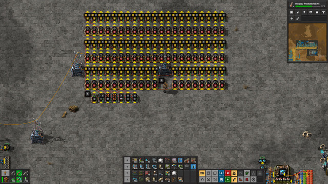
As I had such problems recently, I created a signal recorder. Once a clock is started, it will store selected signals in memory cells. The values of each tick are stored in a seperate cell, so you can easily track how the signals change over time. Overall, 60 such cells are in the blueprint, so you can record a whole second. Here's how it looks.
The clock is started once a condition S is set. This can be done by manually activating the constant combinator, or by using a combinator providing the output if an interesting situation might appear which you want to record.
The input values can be linked to combinators at the bottom which will simply remap them to values as which they will be stored. The blueprint contains five of those, but of course you can add more if needed. Note that I didn't connect the values directly to the decider combinators feeding the input for two reasons:
1. Sometimes you have two signals with the same symbol from different networks. So at least one of them you need to remap to a different value in your signal storage.
2. By connecting several outputs directly to the same network, you could accidently link different networks and break your original circuit design. So to be save I isolate my recorder from the circuit I want to test.
To reset the whole thing and start a new measurement, you can clear all the memory cells easily by shortly deactivating and reactivating the constant combinator "R" which sets all memory cells to 0. To reset the clock you have to remove the red wire connecting its input and output and add it back once the condition S is not active anymore. There are probably smarter versions to do that, but I really wanted to have the clock to be as simple as possible.
