I apologize for this being heavy on words and light on pictures, but honestly, pictures only help so much. I recommend you load up a world and play along, setting up things as I describe them and playing with them, watching the inputs and outputs of your combinators as you do (they're displayed at the bottom of the detail view on the right when they're hovered over, if you've never noticed before). Even if you're following it well enough in your head, it wouldn't hurt to see it in practice.
The sections are in spoilers to prevent this from being unmanagably long. There are a lot more pictures in the practical section towards the end, which those of you who already basically "get" combinators may want to skip down to.
First off, to understand combinators, you have to understand circuit networks. Until now, it was entirely possible to do all the standard, common things with smart chests and inserters without really knowing how the circuit network works, but combinators are a different animal, and it's very helpful to grasp this first.
Circuit Networks - the nitty gritty
Got you head around that? Good. Now on to the actual combinators!Introduction
Each given set of connected wires of the same color constitutes a circuit network. When a circuit network updates, it grabs the outputs from all connected devices that output anything - whether they're chests, combinators, fluid tanks, or anything else that adds network support in the future, doesn't matter. For each network, all the connected objects' outputs are taken and added together to give one value for each signal, and each circuit network can have a signal for every item type, fluid type, plus the 20 abstract signals added in 0.12 (0-9, A-F, and red, green, yellow, and blue). Because each network can have only one value for each of these signals, it's important to pay attention to how they connect, or you will be Surprised when two values you meant to be used separately are suddenly added together to produce a new value. If there are 4 chests connected, then the network's iron value is the total of iron in all four. Combinators will be no different, except combinators can suddenly do things like output a negative number of iron plates.
Note that there are not two circuit networks, red and green - there are as many as you want to make. Any time two wires of the same color connect to the same point, those wires join into one network, but as long as they stay unconnected, they're separate networks with their own set of signal values.
Now, how circuit networks update was not hugely important before 0.12, but it's important to note: when the circuit network is updating, adding up the outputs to arrive at it's new values, those values are not yet being input to anything. It is only after the circuit networks are all updated that the objects update based on input from the circuit network.
Using a simple smart chest -> smart inserter example, if the inserter activates on iron > 100, adding 200 iron to the chest does not actually activate the inserter immediately - there's a very slight delay, basically unnoticable to us humans.

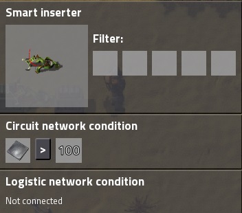
If you threw 200 iron plates in the smart chest, here is a breakdown of what would happen.
cycle 1, phase 1 - the plates were added after the previous cycle.
* The chest updates, and now outputs 200 iron plates.
* The inserter updates, but the circuit network still has the old value, with no iron plates signal.
cycle 1, phase 2
* circuit network updates. circuit network now has 200 for iron plates signal.
cycle 2, phase 1
* chest updates, but no change, still outputs 200 iron plates.
* inserter now gets the 200, and activates.
This would carry on until the chest has less than 100 plates, and then, after another one cycle delay, the inserter will deactivate.
A side note, the inserter only needs its condition to be true for one single cycle - once the inserter sees it's condition true, and decides to do an insert, it doesn't check again until it is finished inserting. Probably a good thing, too - if it checked constantly, then pulling items out of the source chest might cause it's condition to become false, and what would it do then?
Summary
So, to sum-up, circuit networks have a two-phase update. A "snapshot" of the current circuit network signals is taken, and all objects update based on that. Then, in a second phase, the circuit networks themselves update based on changes to the objects' outputs in the first phase.
This whole process happens once per game tick (60 times a second, generally).
Each given set of connected wires of the same color constitutes a circuit network. When a circuit network updates, it grabs the outputs from all connected devices that output anything - whether they're chests, combinators, fluid tanks, or anything else that adds network support in the future, doesn't matter. For each network, all the connected objects' outputs are taken and added together to give one value for each signal, and each circuit network can have a signal for every item type, fluid type, plus the 20 abstract signals added in 0.12 (0-9, A-F, and red, green, yellow, and blue). Because each network can have only one value for each of these signals, it's important to pay attention to how they connect, or you will be Surprised when two values you meant to be used separately are suddenly added together to produce a new value. If there are 4 chests connected, then the network's iron value is the total of iron in all four. Combinators will be no different, except combinators can suddenly do things like output a negative number of iron plates.
Note that there are not two circuit networks, red and green - there are as many as you want to make. Any time two wires of the same color connect to the same point, those wires join into one network, but as long as they stay unconnected, they're separate networks with their own set of signal values.
Now, how circuit networks update was not hugely important before 0.12, but it's important to note: when the circuit network is updating, adding up the outputs to arrive at it's new values, those values are not yet being input to anything. It is only after the circuit networks are all updated that the objects update based on input from the circuit network.
Using a simple smart chest -> smart inserter example, if the inserter activates on iron > 100, adding 200 iron to the chest does not actually activate the inserter immediately - there's a very slight delay, basically unnoticable to us humans.


If you threw 200 iron plates in the smart chest, here is a breakdown of what would happen.
cycle 1, phase 1 - the plates were added after the previous cycle.
* The chest updates, and now outputs 200 iron plates.
* The inserter updates, but the circuit network still has the old value, with no iron plates signal.
cycle 1, phase 2
* circuit network updates. circuit network now has 200 for iron plates signal.
cycle 2, phase 1
* chest updates, but no change, still outputs 200 iron plates.
* inserter now gets the 200, and activates.
This would carry on until the chest has less than 100 plates, and then, after another one cycle delay, the inserter will deactivate.
A side note, the inserter only needs its condition to be true for one single cycle - once the inserter sees it's condition true, and decides to do an insert, it doesn't check again until it is finished inserting. Probably a good thing, too - if it checked constantly, then pulling items out of the source chest might cause it's condition to become false, and what would it do then?
Summary
So, to sum-up, circuit networks have a two-phase update. A "snapshot" of the current circuit network signals is taken, and all objects update based on that. Then, in a second phase, the circuit networks themselves update based on changes to the objects' outputs in the first phase.
This whole process happens once per game tick (60 times a second, generally).
Combinators and Circuit Networks
Combinators work the same way as basic objects like chests and inserters, but are a bit more complicated. Before, everything either sent a signal to the circuit network - like smart chests - or pulled values from it - like smart inserters. Combinators do both, and they have separate contacts for input and output. This means a combinator can actually have two green wires connected - one to input, one to output - without those being automatically joined into one network, and same with red. Still, as before, connecting two green to input or two green to output will combine those into one network. This may seem obvious, but as you make more complex things with combinators, there will be times you will forget and accidentally join two networks without intending to, causing your system to fail in strange and confusing ways. When designing logic systems, you have to think of the networks themselves as entities, because they are.
So, combinators are objects, and update during the object update phase just like everything else. There are three kinds.
Constant Combinators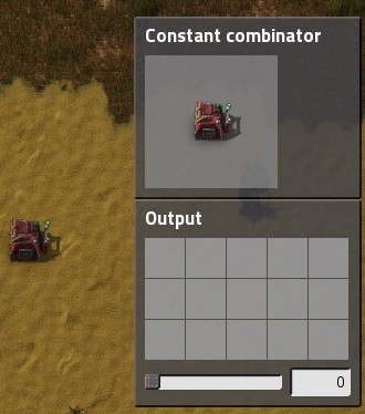
First is constant combinators; these actually don't do input, unlike the others, only output, and you can think of them as being like virtual chests. They don't actually contain objects, but they output signals exactly like a chest containing those objects would.
The difference is, since they're virtual, they can contain impossible things - like 5 of the color blue (and other abstract signals), or -100 iron plates. Whatever values you set in them, they'll otherwise output exactly like the chest would - being added to the totals on the connected circuit networks.
Constant combinators have many uses in logic systems, and you'll also find they're very useful in testing designs. If you want something to happen when there are certain amounts of iron plates on the network, you can test that by adding or removing iron plates, which can be fiddly, or you can just throw down a constant combinator and tell it to output whatever exact numbers you want. It's even worse if the test requires certain levels of fluid in a storage tank!
Decider Combinators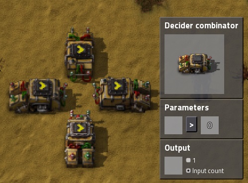
(in this picture, all four have their output in the middle, with the inputs to the outside; it can be tricky at first to tell them apart, but you'll get used to it. The way I first started telling was, when horizontal, looking for the input side's sloped bit, and when vertical, the output end has a visible cross-bar between it's red and green poles.)
Overview
Next are decider combinators. These do comparisons - equal to, greater than, or less than. They can compare two signals, or they can compare one signal to a constant.
Output Modes
They have two output modes - "1" or "input count." Setting them to "output 1" makes them output a count of 1 of the selected type if the condition is true, and output nothing otherwise. In general, values of 0 are not usually sent as signals, so you won't see a signal count of '0' in the info box on the right when selecting them; no signal is treated as a count of 0, though, so it's not usually a problem. There is an exception I'll get to later, though, so keep it in mind.
Setting the output to "input count" means that, if the condition is true, the number output on the signal is the same as the input on the signal selected on the left in the condition. So, if you had a combinator test "iron plates > copper plates" and output signal "coal" as "input count", when the condition is true, the combinator will output the number of iron plates, as a signal on coal. The coal value in the input, if present, is not a factor. If the output type doesn't match the left type in the condition, then when true, it basically converts the signal to the specified output type.
A Note about Inputs
Now, there's an important point about inputs here, which will apply to arithmetic combinators too. The input used in conditions in a decider is the total of the connected red and green networks. The networks are not connected - they still retain their separate values otherwise - but the two signals are combined internally as if they were connected. This can be important to remember.
If you were testing iron > copper, for example, and had a green circuit bringing over info from a copper area and red bringing from an iron, it could be easy to forget that the red network in the iron area actually connects to some chests that have a little copper, too. If so, that copper from red will be added to the copper signal from green.
Keep this in mind, and in general, pay attention to what signals you allow to go on a given circuit network. You can combine unrelated signals into one network - and may want to, to reduce the amount of wiring you have to do - but you have to be careful to keep separate values on separate networks.
Arithmetic Combinators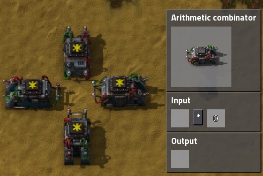
(like before, outputs are in the middle; similar to the deciders, but note the input is somewhat less sloped from the sides, and the cross-bar is more visible from the sides and when output is "up" than on deciders, and not visible at all when the output is "down.")
Overview
Arithmetic combiners are similar to deciders, except they perform some mathematic operation (add, subtract, multiply, or divide) instead of a comparison.
Output
Their output doesn't have the mode option, unlike deciders, and the output count is always the result of the operation. If your combinator was doing "iron plates + copper plates," which came to 100, and set to output as coal, it would output 100 on coal. Whether the input networks had 0 coal or 10000 coal doesn't matter, the result of the operation is the only thing it outputs.
Note that this means you can use an arithmetic combinator set to "<something> + 0" to convert a signal of any type to a signal of any other type - this can be a very handy way to connect to standard circuit blueprints, without having to go through the circuit changing types everywhere to an expected type. You can just design the circuit in the blueprint with an abstract signal, like "A", and use a single arithmetic combinator to convert whatever input signal you're using it on into an "A" signal whenever you place the blueprint. You can do the same with output, to convert some standard output into what you need in a particular situation.
Special inputs - Anything, Everything, and Each
Ok, that's the theory. On to some practical stuff!Now, there are three special signals I've saved for the end - everything, anything, and each. They appear as asterisks (*) on red, green, and yellow, respectively - but don't let the colors fool you, they have nothing to do with red and green circuit networks, and all act on the internal, combined total of the connected networks like all other conditions!
Everything
Everything tests just that - every signal it's getting. The condition will be true only if it was true for every one of those signals. For example, a decider with "everything > 10" with it's input connected to a constant combinator outputting only "iron plates = 11" will test true. Add a second signal to the constnat combinator, "copper plates = 1", and now it will test false, because it is getting a copper plates signal, and it is not greater than 10. Change it to 11 as well, and the condition will be true again.
Now, remember when I said 0 values tend not to actually be sent as signals? Here's where that's important. If you have 1 copper and 11 iron, the "everything>10" test will fail, but if you take away that 1 copper, the test will pass. 0 copper is no copper signal, and will not be considered in the test at all! Bear this in mind, as it sometimes limits the usefulness of "everything" as a setting.
The output when an "everything" test is true be the sum of all the counts of all the inputs. So, in the iron and copper both 11 example, it will output the count "22" on whatever item or abstract signal you select for output.
Everything can also be used as output on deciders, in which case, if the test is true, all the inputs will be passed to output if the condition is true.
Anything
Anything works similarly, but instead of testing true only if every input signal passes, it tests true if at least one does. So iron=11 and copper=1 would give true, as would iron=11 and copper=11; iron=1 and copper=1 would fail, as would no signals at all. Anything can never be used as an output type.
Each
Each is a bit more complicated. Each also performs the test on each input signal, but instead of being true or false once, it gives a true or false result for each one individually.
Take our examples earlier:
if the test is "each > 10," and output is set to "coal" and outputs 1, if iron and copper are both 1, each will test false, and there will be no coal output.
If iron is increased to 11, iron will test true, and it will output 1 on coal.
If iron and copper are both 11, both will test true, and it will output 1 on coal twice, meaning it actually outputs 2 on coal.
So, using output "1", "each" in your condition means it outputs the number of input signals that passed the test.
If you output "input count," things get odder. In our example above, with iron and copper both = 11, the coal output would be 22.
With iron=11 and copper=1, the output would be 11.
With both = 1, it would not output coal.
I'm sure this would be useful in some circumstances, but I have no idea when or why! Let me know if you find one!
Each as output
When you have "each" selected as input, you can also select "each" as your output signal, in which case it will pass through all input signals that pass the condition.
Iron and Copper both = 11, it would output both iron and copper as 11
Iron and Copper both = 1, it would output nothing.
With "each" as output and 1 selected, it will just output a signal of 1 on each signal type that passes the test.
Deciders vs Arithmetic
All of special signals can be used as described with deciders, but only as the first, left side of the comparison. Arithmetic can only use "each," again on the left. Note that in the case of arithmetic, the outputs work the same, except in place of the input signals, the result of the operation will be used - "each * 2" output to coal would take each input, multiply it by 2, add all of those together, and output that total on coal. Again, when this would be useful, I have no idea.
S-R Latches
In simple terms, an S-R latch holds a single true/false value. It has two inputs - set and reset (hence the S-R). A value of true (signal 1) to input will set the latch to true; a signal of 1 to reset will set it to false(0). You can make an s-r latch with combinators quite easily...
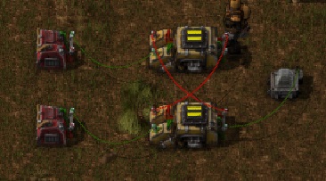
and here's a blueprint string (see the note below about blueprints and latches)
[quote]H4sIAAAAAAAA/9WS0WrDMAxFf6X42SmNuz4V7UfKCJ7tDIEjB8cZDSb/PscJo+3WtRuDsUcn0tXV0dVuZZ2SdlVBNBQwoOkgRpKNAaYcdUFSKJRrnpFkcJ7x
1nWpyhHEIxRiveMDFJv1buQ12mD81N3hC0kLMQxtUnlFH3ppGZ9F55/Fho1cuZ4CbDiSNkcox3Hky2RtFGrjrw4u36dq9EblzyLpEc2P5OLASvYE0RudHOXV
hgo17LhCr3oM00OkiS/eGDoryUYOTNxsnwqnLUjjMnTxDbFG34XqfhAz6MQibdxKP20MDBh3fWj77wi1Q5WxVrV3TYWUuoHV0naGnfDtGmltYWXTnnPd5ntm
sJ/B/MjqEucFj+XnL/F4PF3h3nCWf5HN8ifRFLej+fBFNMVFND9p3/67wI4cVTYal0Pwq0dIB5prBL+ekKS49yb0nlbV3pB+A7+5AAsABQAA[/quote]
The constant combinators on the left are just for putting in test inputs. I set it all up using signal 'A', but any signal will work.
The two deciders are configured identically - they simply test 'A = 0' and output 1 on A when true, like so:
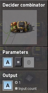
You can use the same shift-click copying you would on factories or anything else, they really are identical in settings.
For wiring, it should be obvious in the screenshot since I spaced them out, but each one's output is hooked to the others' input. Simple as that, 2 identical deciders and 2 wires, and you have a latch.
The top input is "set," the bottom "reset," and both are activated by a signal on A. It doesn't have to be a 1, but anything except -1 or 0 should work fine.
Here, I wired the bottom to a light, set to activate if A > 0. The latch is currently outputing 0, but if I go into the top combinator and set "A = 1" I get this...
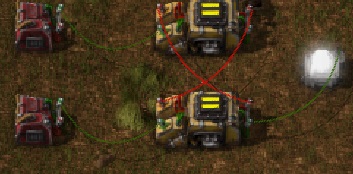
The latch is on, the light is on. It will stay that way even if I remove the top combinator completely...
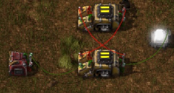
Reset, on the bottom combinators' input, works the same way. A signal will cause it to turn off, and stay off even when the signal goes away.
Both inputs to an s-r latch shouldn't, ideally, be true at the same time, but in this case, if they are, the latch will turn off. Whichever signal stays true longer, will win - if reset turns off first, the latch will be set, otherwise it will reset.
Undefined State
Now, time for that note about these latches and blueprints. When placed with blueprints, a latch like this will sometimes wind up in an undefined state. This means it will rapidly flick itself on and off, in this case causing the light to flicker.
You can tell if this has happened because there is a little light that flashes on each combinator when it changes - that light will be doing it's best feeble strobe on both combinators when this happens.
The reason this happens is that, if both combinators are set up and configured at exactly the same time, then both will have 0 for input, and so both will output true. Since each takes the other as input, the next cycle, both will see the others' true, and change to false. This repeats, cycle after cycle, until something happens to interrupt it. (You can force this to happen by connecting both to a single constant combinator, setting it to output 1, and then setting it back to 0, if you want to see this in action)
You can interrupt this by sending a "true" to one or the other, which will force it to settle down. Disconnecting and reconnecting one of the wires will also stop it, or just changing one's output signal to something else then changing it back.
This undefined state can happen in use if you're not careful - if set and reset are both true, and both become false at the exact same time, or if a set or reset signal lasts exactly one cycle before turning off. Either of these would be pretty rare if the signals are coming from your factory somewhere, but can happen if the inputs are coming from more circuit logic. There are ways to "sanitize" the inputs if the problem does come up, which I'll get to in the 2nd practical example, pulse generators.
I thought you said practical - what's this for?
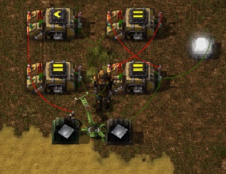
Some of you are wondering what use these things are; well, take a classic smart inserter use, being active until some target amount is reached, say, 200 iron in the chest. Now, suppose you wanted to start and stop based on different conditions - start inserting if it drops below 50, and then keep inserting until it reaches 200. An s-r latch will let you do that easily.
[quote]H4sIAAAAAAAA/9WVYW/bIBCG/0rEZ1zZbr196KjU31FNFoNLdxIGC85VI+T/Puxka0yyNM22SPsWwuv3uId7be1WxilpVq2IYAkJIYgYrexAMA0KNfhCue4b
WknOM967kETOivgqippvRFHdNCPX6EHN/9dcOWu3i2T1xCr2VUQPOtnOFTYtanHHFXo1IE2LahxH/sTqSfjsAexCWufScaqgcVdgd0gR1+gDtQGfrTQi0qZP
HSBBx/i2G/TOFr2RBGx2CCQtiaZMv7te+qk9wb4w7gbqh9zoBT0N0vz02m4Wj7NTv2mVGyy1a++6Fm16WrC1NCEVSoc9E2Z1MctmH1CdKh4yrDLJL9wnvT4I
+xSjHe0lbPHPYIdOGlMY2fVLyLc3zYS5nDAfQ3tILoebAdlt/iUgDx8ZmDl95SUDUy0vme9tfT4ZxT+ZjvejWJfXGo9zsngR2fr9KN6dG8X8vXfE63Zxd5/+
57h6KtAG8AT5mJdzZutzruPq8a0yQAc9qe8QKGuoemvook/lXg0CMMdqvDFLYlSzfUSrYZrt32Ygie890ODtqr0Hq38A+ZMJQh0IAAA=[/quote]
Instead of hooking the chest directly to the inserter, you would hook the chest to a pair of deciders, one set to the starting condition - iron plates < 50 - and the other to the ending condition, iron plates = 200. Put these next to an s-r latch, with the first connected to "set" and the second connected to "reset," then hook the output of the latch to the smart inserter. This is a simple example; the start and stop conditions can be anything you want, and using more combinator logic, they can be as complicated as you like.

and here's a blueprint string (see the note below about blueprints and latches)
[quote]H4sIAAAAAAAA/9WS0WrDMAxFf6X42SmNuz4V7UfKCJ7tDIEjB8cZDSb/PscJo+3WtRuDsUcn0tXV0dVuZZ2SdlVBNBQwoOkgRpKNAaYcdUFSKJRrnpFkcJ7x
1nWpyhHEIxRiveMDFJv1buQ12mD81N3hC0kLMQxtUnlFH3ppGZ9F55/Fho1cuZ4CbDiSNkcox3Hky2RtFGrjrw4u36dq9EblzyLpEc2P5OLASvYE0RudHOXV
hgo17LhCr3oM00OkiS/eGDoryUYOTNxsnwqnLUjjMnTxDbFG34XqfhAz6MQibdxKP20MDBh3fWj77wi1Q5WxVrV3TYWUuoHV0naGnfDtGmltYWXTnnPd5ntm
sJ/B/MjqEucFj+XnL/F4PF3h3nCWf5HN8ifRFLej+fBFNMVFND9p3/67wI4cVTYal0Pwq0dIB5prBL+ekKS49yb0nlbV3pB+A7+5AAsABQAA[/quote]
The constant combinators on the left are just for putting in test inputs. I set it all up using signal 'A', but any signal will work.
The two deciders are configured identically - they simply test 'A = 0' and output 1 on A when true, like so:

You can use the same shift-click copying you would on factories or anything else, they really are identical in settings.
For wiring, it should be obvious in the screenshot since I spaced them out, but each one's output is hooked to the others' input. Simple as that, 2 identical deciders and 2 wires, and you have a latch.
The top input is "set," the bottom "reset," and both are activated by a signal on A. It doesn't have to be a 1, but anything except -1 or 0 should work fine.
Here, I wired the bottom to a light, set to activate if A > 0. The latch is currently outputing 0, but if I go into the top combinator and set "A = 1" I get this...

The latch is on, the light is on. It will stay that way even if I remove the top combinator completely...

Reset, on the bottom combinators' input, works the same way. A signal will cause it to turn off, and stay off even when the signal goes away.
Both inputs to an s-r latch shouldn't, ideally, be true at the same time, but in this case, if they are, the latch will turn off. Whichever signal stays true longer, will win - if reset turns off first, the latch will be set, otherwise it will reset.
Undefined State
Now, time for that note about these latches and blueprints. When placed with blueprints, a latch like this will sometimes wind up in an undefined state. This means it will rapidly flick itself on and off, in this case causing the light to flicker.
You can tell if this has happened because there is a little light that flashes on each combinator when it changes - that light will be doing it's best feeble strobe on both combinators when this happens.
The reason this happens is that, if both combinators are set up and configured at exactly the same time, then both will have 0 for input, and so both will output true. Since each takes the other as input, the next cycle, both will see the others' true, and change to false. This repeats, cycle after cycle, until something happens to interrupt it. (You can force this to happen by connecting both to a single constant combinator, setting it to output 1, and then setting it back to 0, if you want to see this in action)
You can interrupt this by sending a "true" to one or the other, which will force it to settle down. Disconnecting and reconnecting one of the wires will also stop it, or just changing one's output signal to something else then changing it back.
This undefined state can happen in use if you're not careful - if set and reset are both true, and both become false at the exact same time, or if a set or reset signal lasts exactly one cycle before turning off. Either of these would be pretty rare if the signals are coming from your factory somewhere, but can happen if the inputs are coming from more circuit logic. There are ways to "sanitize" the inputs if the problem does come up, which I'll get to in the 2nd practical example, pulse generators.
I thought you said practical - what's this for?
Some of you are wondering what use these things are; well, take a classic smart inserter use, being active until some target amount is reached, say, 200 iron in the chest. Now, suppose you wanted to start and stop based on different conditions - start inserting if it drops below 50, and then keep inserting until it reaches 200. An s-r latch will let you do that easily.

[quote]H4sIAAAAAAAA/9WVYW/bIBCG/0rEZ1zZbr196KjU31FNFoNLdxIGC85VI+T/Puxka0yyNM22SPsWwuv3uId7be1WxilpVq2IYAkJIYgYrexAMA0KNfhCue4b
WknOM967kETOivgqippvRFHdNCPX6EHN/9dcOWu3i2T1xCr2VUQPOtnOFTYtanHHFXo1IE2LahxH/sTqSfjsAexCWufScaqgcVdgd0gR1+gDtQGfrTQi0qZP
HSBBx/i2G/TOFr2RBGx2CCQtiaZMv7te+qk9wb4w7gbqh9zoBT0N0vz02m4Wj7NTv2mVGyy1a++6Fm16WrC1NCEVSoc9E2Z1MctmH1CdKh4yrDLJL9wnvT4I
+xSjHe0lbPHPYIdOGlMY2fVLyLc3zYS5nDAfQ3tILoebAdlt/iUgDx8ZmDl95SUDUy0vme9tfT4ZxT+ZjvejWJfXGo9zsngR2fr9KN6dG8X8vXfE63Zxd5/+
57h6KtAG8AT5mJdzZutzruPq8a0yQAc9qe8QKGuoemvook/lXg0CMMdqvDFLYlSzfUSrYZrt32Ygie890ODtqr0Hq38A+ZMJQh0IAAA=[/quote]
Instead of hooking the chest directly to the inserter, you would hook the chest to a pair of deciders, one set to the starting condition - iron plates < 50 - and the other to the ending condition, iron plates = 200. Put these next to an s-r latch, with the first connected to "set" and the second connected to "reset," then hook the output of the latch to the smart inserter. This is a simple example; the start and stop conditions can be anything you want, and using more combinator logic, they can be as complicated as you like.
Pulse Generators
Sometimes it's useful to take a signal or condition, which becomes true and stays true for some sustained (or very short) period of time, and normalize it, make it into something predictable and controllable. Pulse generators are good at this.
This is the most basic pulse generator I know how to make. When it's condition is true, it outputs a signal of 1 for exactly 1 cycle. The decider is set to "Iron plates > 0" and outputs A = 1; the arithmetic is set to "A * -1" and outputs A. The light activates on A = 1
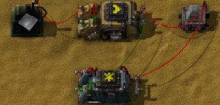
When iron is added to the chest, first the decider updates and starts sending out 1 on a. The next cycle, the light sees this and turns on, and the arithmetic combiner gets the new value and starts outputing -1. The cycle after that, the -1 is added to the 1 on the red output network, which puts A back to 0, and the light turns off.
When the iron is removed from the chest, the same happens in reverse - first the decider starts outputting 0. Next cycle, the light is now seeing -1 - because the arithmetic hasn't updated yet - but this still isn't = 1, so it stays off. This same cycle, the arithmetic updates, and so will go back to outputting 0.
By itself, this is enough to, for example, make an inserter operate once when some condition becomes true, rather than continuously operating while the condition is true.
[quote]H4sIAAAAAAAA/7VU226jMBT8lciPK1MFsulL5Ur7HVWFvPZJeyRfkH1YFaH8+9qBTQIkUdNVeQLGzJwZj9F+ZbySZlWLHhwhIUTR905aECxaGahQ7xCJ8cbH
hHon+g9RbB62vBPF+mG758o7BypD6csXVrJX0QfQieVA2NWoRcUVBtUi5Ydyny8+imhQqCEUytvf6CT5MNMqj0oawyCU+T6hmoX4C6suYZsEvQUAN3n7czFn
FtI46oyzin6HIVId8c1JI3rqmmQECSzjgykM3hWNkQTswBBJOhLrdGsbGbJJwZ4Z9y017ZznDwZqpflHNYDFrwNR09XKt47qXfC2Rpe+FmwnTUw6p0jTvhlT
GGmbaZTl/+xaleivBDWFHhexjUsvx3bL7phbOclNnFuVAendAqG6XaDyM/1Z9mGWwM06zUyfJvuy7zS5byDZziOzH/f25bwRBGAuneShEjmd8/akU48uQiCY
ZVkdl999GJcJfWMtrvrdnPzuOarDHD06DSkKfqtSiXpYVvGr/63E+RSA2uBW9RM4/RdHCeyMXQUAAA==
[/quote]
Pulses and S-R Latches
Now, I mentioned in s-r latches using these to normalize input, but in this form, they would actually break your latch, as 1 tick pulses will cause them to go into an undefined state! The -1 signal when the condition becomes false is also a problem for the latch.
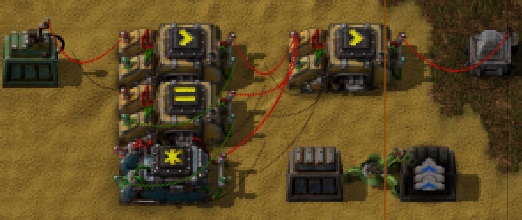
The first problem can be addressed by lengthening the pulse to 2 cycles, by inserting a second decider between the 1st and the arithmetic combinators, set to "A=1 output A," and chaining the inputs through it instead of connecting directly, like so:
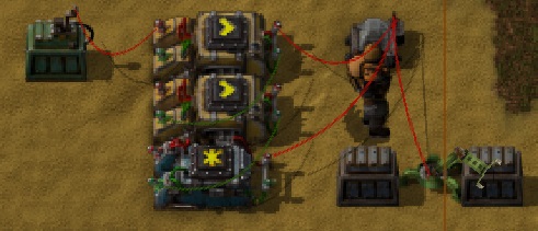
Now, cycle 1, the top combiner outputs 1; cycle 2, the light turns on, and the second combinator changes outputs to 1; the third cycle, the arithmetic outputs -1, and then the light will turn off, after 2 cycles instead of 1.
This deals with the length of the pulse; to get rid of the -1, we have to insert yet another decider, this time before the light. It should be set to "A > 0 output A=1"
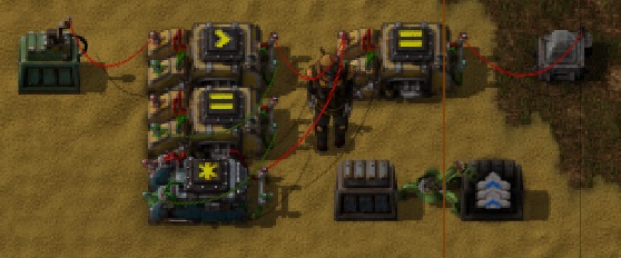
Now, there is one last condition we aren't handling here - what if the signal itself only lasts one cycle? with this setup, it will output 1 for 1 cycle, which is no good if we're hooking to an r-s latch! Since we've added our normalizer and delay combinators, though, we can fix it pretty easily. Just connect the middle, delay combinator to the normaliser, and change the arithmetic to output "A * -2" instead of "A * -1." If the signal turns off after 1 cycle, this combinator will still be outputing a 1 one cycle behind the first, and the signal will be effectively extended.
[quote]H4sIAAAAAAAA/72VwW7bMAyGXyXQcZCL2q57KTRgz1EMhiYxLQFZMih6WGDk3Sc5WVu7TeFkQX2yQYk/+Ym/ZcPGBaPdplUjeEZGiGocve5Aidhp4sI8Q2Qh
+xBTNHg1/lFFfdPInSpub5q9NMF7MDmUdj6KUvxUI4FNWaaEuxatqqRBMgNy/ij3+ZFHEQsGLVBhQvcLveZAC63yRckiHYRyvhWqWUg+iuqjWL2oSD4RgJ8t
ad4VnVUtHkWPhatxixS5jfjktVMj7/rUFTJ0Qh46RAq+6J1mEFOGyNqzuk2vXa8pd6zEdyHDwP2wzPMbiQft/qU6BIsfU6J+15oweG63FLoWfdqtxFa7mHTW
860uxjs71CoJnkA3D93PQ6dP6O484p+R+mLkyTfOFU53/Rz13ZmuqZeo5jiOwavhONeUq4bmva2qtQOwwqL3/2HRFYTKGSF1rYFhGmbzogn5uQNG8znw8jLg
zaXAFzRfy7wYaGoj9JB45vrFt3OBvvUYA7iP7qZyMllG9daP6R5DH4EYlr+/l+VLslfz2XKK1nRRv3axl2imOkb0FlKD8qRH0+IHAh7Ib9oH8PYvna9kUt4H
AAA=
[/quote]
Rising vs Falling Edges
A note, this generates a pulse on the "rising edge," meaning it's true only in the instant when the condition goes from false to true; using this last setup, if you changed the new combinator from "A>0 output A=1" to "A<0 output A=1" you would generate a pulse on the falling edge instead, when the condition goes from true to false. By placing two combiners, one with each setting, you could generate a pulse whenever the signal changes either way (this could be done with single not-equal combiner, but sadly, this is not currently an option. Maybe in 0.13!)
Use As Needed
The properly sanitized and lengthened pulse geneator is suitable for use with the above r-s latches, and will ensure they don't go undecided - though as I said earlier, they won't always, or even usually, be necessary, if you're worried about space and resources. You may not need anything at all, or just the last decider to normalize the value and remove negatives may be enough. In cases like the practical example earlier, with iron conditions <50 and =200 to start and stop an inserter, they would be completely unnecessary - both conditions can never be true at the same time, and it would be virtually impossible, short of custom scripting in lua, for one to become true for exactly one cycle and then become false again.
This is the most basic pulse generator I know how to make. When it's condition is true, it outputs a signal of 1 for exactly 1 cycle. The decider is set to "Iron plates > 0" and outputs A = 1; the arithmetic is set to "A * -1" and outputs A. The light activates on A = 1

When iron is added to the chest, first the decider updates and starts sending out 1 on a. The next cycle, the light sees this and turns on, and the arithmetic combiner gets the new value and starts outputing -1. The cycle after that, the -1 is added to the 1 on the red output network, which puts A back to 0, and the light turns off.
When the iron is removed from the chest, the same happens in reverse - first the decider starts outputting 0. Next cycle, the light is now seeing -1 - because the arithmetic hasn't updated yet - but this still isn't = 1, so it stays off. This same cycle, the arithmetic updates, and so will go back to outputting 0.
By itself, this is enough to, for example, make an inserter operate once when some condition becomes true, rather than continuously operating while the condition is true.
[quote]H4sIAAAAAAAA/7VU226jMBT8lciPK1MFsulL5Ur7HVWFvPZJeyRfkH1YFaH8+9qBTQIkUdNVeQLGzJwZj9F+ZbySZlWLHhwhIUTR905aECxaGahQ7xCJ8cbH
hHon+g9RbB62vBPF+mG758o7BypD6csXVrJX0QfQieVA2NWoRcUVBtUi5Ydyny8+imhQqCEUytvf6CT5MNMqj0oawyCU+T6hmoX4C6suYZsEvQUAN3n7czFn
FtI46oyzin6HIVId8c1JI3rqmmQECSzjgykM3hWNkQTswBBJOhLrdGsbGbJJwZ4Z9y017ZznDwZqpflHNYDFrwNR09XKt47qXfC2Rpe+FmwnTUw6p0jTvhlT
GGmbaZTl/+xaleivBDWFHhexjUsvx3bL7phbOclNnFuVAendAqG6XaDyM/1Z9mGWwM06zUyfJvuy7zS5byDZziOzH/f25bwRBGAuneShEjmd8/akU48uQiCY
ZVkdl999GJcJfWMtrvrdnPzuOarDHD06DSkKfqtSiXpYVvGr/63E+RSA2uBW9RM4/RdHCeyMXQUAAA==
[/quote]
Pulses and S-R Latches
Now, I mentioned in s-r latches using these to normalize input, but in this form, they would actually break your latch, as 1 tick pulses will cause them to go into an undefined state! The -1 signal when the condition becomes false is also a problem for the latch.
The first problem can be addressed by lengthening the pulse to 2 cycles, by inserting a second decider between the 1st and the arithmetic combinators, set to "A=1 output A," and chaining the inputs through it instead of connecting directly, like so:

Now, cycle 1, the top combiner outputs 1; cycle 2, the light turns on, and the second combinator changes outputs to 1; the third cycle, the arithmetic outputs -1, and then the light will turn off, after 2 cycles instead of 1.
This deals with the length of the pulse; to get rid of the -1, we have to insert yet another decider, this time before the light. It should be set to "A > 0 output A=1"

Now, there is one last condition we aren't handling here - what if the signal itself only lasts one cycle? with this setup, it will output 1 for 1 cycle, which is no good if we're hooking to an r-s latch! Since we've added our normalizer and delay combinators, though, we can fix it pretty easily. Just connect the middle, delay combinator to the normaliser, and change the arithmetic to output "A * -2" instead of "A * -1." If the signal turns off after 1 cycle, this combinator will still be outputing a 1 one cycle behind the first, and the signal will be effectively extended.

[quote]H4sIAAAAAAAA/72VwW7bMAyGXyXQcZCL2q57KTRgz1EMhiYxLQFZMih6WGDk3Sc5WVu7TeFkQX2yQYk/+Ym/ZcPGBaPdplUjeEZGiGocve5Aidhp4sI8Q2Qh
+xBTNHg1/lFFfdPInSpub5q9NMF7MDmUdj6KUvxUI4FNWaaEuxatqqRBMgNy/ij3+ZFHEQsGLVBhQvcLveZAC63yRckiHYRyvhWqWUg+iuqjWL2oSD4RgJ8t
ad4VnVUtHkWPhatxixS5jfjktVMj7/rUFTJ0Qh46RAq+6J1mEFOGyNqzuk2vXa8pd6zEdyHDwP2wzPMbiQft/qU6BIsfU6J+15oweG63FLoWfdqtxFa7mHTW
860uxjs71CoJnkA3D93PQ6dP6O484p+R+mLkyTfOFU53/Rz13ZmuqZeo5jiOwavhONeUq4bmva2qtQOwwqL3/2HRFYTKGSF1rYFhGmbzogn5uQNG8znw8jLg
zaXAFzRfy7wYaGoj9JB45vrFt3OBvvUYA7iP7qZyMllG9daP6R5DH4EYlr+/l+VLslfz2XKK1nRRv3axl2imOkb0FlKD8qRH0+IHAh7Ib9oH8PYvna9kUt4H
AAA=
[/quote]
Rising vs Falling Edges
A note, this generates a pulse on the "rising edge," meaning it's true only in the instant when the condition goes from false to true; using this last setup, if you changed the new combinator from "A>0 output A=1" to "A<0 output A=1" you would generate a pulse on the falling edge instead, when the condition goes from true to false. By placing two combiners, one with each setting, you could generate a pulse whenever the signal changes either way (this could be done with single not-equal combiner, but sadly, this is not currently an option. Maybe in 0.13!)
Use As Needed
The properly sanitized and lengthened pulse geneator is suitable for use with the above r-s latches, and will ensure they don't go undecided - though as I said earlier, they won't always, or even usually, be necessary, if you're worried about space and resources. You may not need anything at all, or just the last decider to normalize the value and remove negatives may be enough. In cases like the practical example earlier, with iron conditions <50 and =200 to start and stop an inserter, they would be completely unnecessary - both conditions can never be true at the same time, and it would be virtually impossible, short of custom scripting in lua, for one to become true for exactly one cycle and then become false again.
Clocks and Timers
A clock, in circuit terms, is a circuit that emits pulses at some regular interval. They're useful in control systems. Making them with combinators is surprisingly easy.
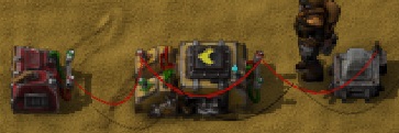
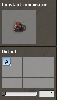
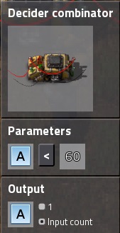
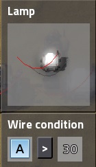
This is a basic 1-second clock. It's output cycles A from 1 to 60 then repeats. The light, set to activate if A > 30, will blink, on for half a second, then off for half a second.
Unlike the earlier examples, this constant combinator isn't for test purposes, but is part of the circuit. The decider works because of the way it feeds back into itself. Initially it gets A=1 as it's input. This is less than 60, so it outputs that A value, 1 - but it outputs it into the same network, which means it is added to the existing value, giving A=2. Next cycle, it's still less than 60, and it outputs it's input - which is now A=2. This repeats until 60, when it becomes false, and it outputs 0 and starts over. Remove the constant combinator and it will freeze in place, whatever it's output is at the moment, that is it's input - nothing to add to without the constant combinator providing a 1 - and so it will stay unless something changes.
Now, if you replaced that constant combinator 1 with a signal from some other logic, the clock will only run while the signal is true. This could be used to, for example, have lights that blink to warn you when levels of something drop too low.

Here, the new decider that replaces the constant one is set to "iron = 0 output A=1," so the clock will only run, and the light blink, when the chest doesn't have any iron in it. Of course, when the chest has iron, it will stop the timer at whatever value it currently has, meaning the light may be on or off, it just won't be blinking anymore, so not ideal, but it's a start.
If we want the light to be off when it's not blinking, we can add an "and" gate between the clock and the light.
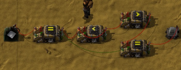
The first combinators are unchanged; the new one on the top is set to the light's old condition, "A > 30", and outputs A = 1. The new one is simply "A = 2" and outputs "A = 1" and the light is as before, on when "A = 1" The light will now be off when it's not actively blinking.
Blueprint of that last version: [quote]H4sIAAAAAAAA/72U3W7jIBCFXyXiGqLY+bnpstI+R1RZLEy6I2GwYFw1Qn73Yiddxd52W0dJ74wZzgzfGcb4hfVa2UUlEzhCQogyJadqkMyARgNBaF//RqfI
B8YbH3OQdzK9yA0/SrFabjtuMIAefpdce+dOi6y0ZwV7lCmAyapDgmOFJp/UGHSL1C/Kruv4npXvBW4vA4uuj8z6Bs/y5wplOmCIVEV8csrKRMcml/+MgVpl
GT/d5rQpfrFBIpJyJNer/F03KvSXk+wn476lpp2j1Bwr7VtH1SH4ukKXT0t2UDYC66s9o4y1CiT0H4g0Zig2y23GOFD8Crn1P0D+5vjMLlG+JZpr1/8c2kwK
4k8BwN3MRCSo37hj8E40VhFceji2UN7Nws/wFtfSnTwG/pHbM1y41Cju+4R2xYj/j1vxp9DOwt8Po+Ia/MWE8TsN/GUbdjfHW35Td+cBZa2wqm7GWHfzxtN2
SmpM47x5NY3puB4SoB60EzoD/TP8sF9y8EMAaoNbVA/gzCvFcmMr/QYAAA==
[/quote]
Now, timers are related to clocks, and can be based on them. This one is probably not optimal, but it will hopefully be easy to understand as it simply combines the clock I just showed you with an r-s latch and pulse generator like I showed you earlier. As always the pulse generator may or may not be necessary; in the test setup, the input signal stays on until I remove the iron from the chest, so I'm using one. If your input signal is itself a pulse, or will always turn off by the time the timer is finished, then you can skip it.
[quote]H4sIAAAAAAAA/9WWbW+bMBDHv0rkl5OpAoUsVetK+xzVhDzbaU8yNjJHtQjlu89O2BbIQ4EWbeVV0Jn73/3ufBdpF9oKrhc5a5RBQFAVaxrDC8VIVXCHkXhR
FRJa2spbrWHNTxalNxndsii+yXZUWGOUCCb/5ROJyXfWOCW9l73DbQ6SJVSAEzVgeIl34aGtiFQCpHKRsMUPMByt62klf5QkuINQ8DdANQjRJ5Kcs6W9iOiz
U8p0jtyeBB1UJbSibeCs2YCrMK/g2XDNGtyWPitAVRB6yBCcNVGpOSqy91AhN8iW/mdRchcyZoQRamss676fV3BYc/3b1cEYfds7Kre5sLXBfONskYPxXzOy
4bryOmP5LofwPUXUqWtyhPv06Nd30LxGocUZz4MTXT2KZjy5WXso6SV0yZWmvpuXcbdlH/8V43Qy46wH8sylj5dDYWdd2McFW89bh1W32R/mKoSf/1pHmhdl
twCrkdP/lGmXR2v8sL48SoE7wJdCIYjrA3Di/Lsd2iz9ddMj8DfMyRCimNpSeQYhfvJlbE+MnHGDeL11/a5si27LfPwVytbzzLLR6zedCjO9vC+Gz7C5Mf8v
f3IC5WQK5bu3N8Z64nY+rtjqrOfscxdnR0HsA23ASBXmxsVi+cP3TmHtzCK/V0b+AsUB0N2XDAAA
[/quote]
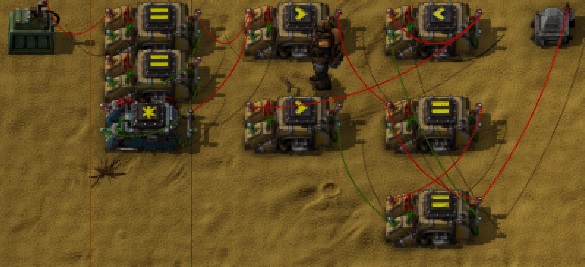
On the left you should recognize the normalized pulse generator I talked about for using with r-s latches. It is exactly as before, except the condition - in the top decider - has been changed to "iron = 0" instead of "iron > 0."
To the right of that, next to the lamp, is the clock, like the first I showed; it's set to "A<60" and outputs A, as before.
The two below the clock are the r-s latch, exactly as before.
The extra one, to the left of the r-s latch, is set to "A > 57." That number is deliberate, set to the clock's upper limit minus 3. Any higher and it won't output true long enough to properly reset the latch, and the whole thing will become undetermined.
The result: when the chest becomes empty, a pulse is sent and the latch turns on. This turns on the clock, which begins counting up.
When the clock approaches 60, a reset signal is sent to the latch, which turns off just as the clock reaches 0. If you work through exactly what happens, cycle by cycle, you'll see this is why the new decider is at 60 - 3 or 57 rather than 60 - 2, which would be 58.
And so, we took an input condition - chest out of iron - and generated a timed output signal for 1 second. You could use another pulse generator on the output, triggered on the falling edge like I mentioned in that section, to turn this into a pulse, generated 1 second after the condition became true. By changing the values 60 and 57, you can adjust the timing to anything you want - though the minimum is 3 cycles for this particular design. (for shorter times than that, using a series of deciders to delay a signal, one per cycle, will be easier and far simpler). The rule is just 60 * the number of seconds you want for the clock, and that minus three for the decider that connects the clock to reset, so for a minute, it would be 60*60 = 3600 and 2597.


This is a basic 1-second clock. It's output cycles A from 1 to 60 then repeats. The light, set to activate if A > 30, will blink, on for half a second, then off for half a second.
Unlike the earlier examples, this constant combinator isn't for test purposes, but is part of the circuit. The decider works because of the way it feeds back into itself. Initially it gets A=1 as it's input. This is less than 60, so it outputs that A value, 1 - but it outputs it into the same network, which means it is added to the existing value, giving A=2. Next cycle, it's still less than 60, and it outputs it's input - which is now A=2. This repeats until 60, when it becomes false, and it outputs 0 and starts over. Remove the constant combinator and it will freeze in place, whatever it's output is at the moment, that is it's input - nothing to add to without the constant combinator providing a 1 - and so it will stay unless something changes.
Now, if you replaced that constant combinator 1 with a signal from some other logic, the clock will only run while the signal is true. This could be used to, for example, have lights that blink to warn you when levels of something drop too low.

Here, the new decider that replaces the constant one is set to "iron = 0 output A=1," so the clock will only run, and the light blink, when the chest doesn't have any iron in it. Of course, when the chest has iron, it will stop the timer at whatever value it currently has, meaning the light may be on or off, it just won't be blinking anymore, so not ideal, but it's a start.
If we want the light to be off when it's not blinking, we can add an "and" gate between the clock and the light.

The first combinators are unchanged; the new one on the top is set to the light's old condition, "A > 30", and outputs A = 1. The new one is simply "A = 2" and outputs "A = 1" and the light is as before, on when "A = 1" The light will now be off when it's not actively blinking.
Blueprint of that last version: [quote]H4sIAAAAAAAA/72U3W7jIBCFXyXiGqLY+bnpstI+R1RZLEy6I2GwYFw1Qn73Yiddxd52W0dJ74wZzgzfGcb4hfVa2UUlEzhCQogyJadqkMyARgNBaF//RqfI
B8YbH3OQdzK9yA0/SrFabjtuMIAefpdce+dOi6y0ZwV7lCmAyapDgmOFJp/UGHSL1C/Kruv4npXvBW4vA4uuj8z6Bs/y5wplOmCIVEV8csrKRMcml/+MgVpl
GT/d5rQpfrFBIpJyJNer/F03KvSXk+wn476lpp2j1Bwr7VtH1SH4ukKXT0t2UDYC66s9o4y1CiT0H4g0Zig2y23GOFD8Crn1P0D+5vjMLlG+JZpr1/8c2kwK
4k8BwN3MRCSo37hj8E40VhFceji2UN7Nws/wFtfSnTwG/pHbM1y41Cju+4R2xYj/j1vxp9DOwt8Po+Ia/MWE8TsN/GUbdjfHW35Td+cBZa2wqm7GWHfzxtN2
SmpM47x5NY3puB4SoB60EzoD/TP8sF9y8EMAaoNbVA/gzCvFcmMr/QYAAA==
[/quote]
Now, timers are related to clocks, and can be based on them. This one is probably not optimal, but it will hopefully be easy to understand as it simply combines the clock I just showed you with an r-s latch and pulse generator like I showed you earlier. As always the pulse generator may or may not be necessary; in the test setup, the input signal stays on until I remove the iron from the chest, so I'm using one. If your input signal is itself a pulse, or will always turn off by the time the timer is finished, then you can skip it.

[quote]H4sIAAAAAAAA/9WWbW+bMBDHv0rkl5OpAoUsVetK+xzVhDzbaU8yNjJHtQjlu89O2BbIQ4EWbeVV0Jn73/3ufBdpF9oKrhc5a5RBQFAVaxrDC8VIVXCHkXhR
FRJa2spbrWHNTxalNxndsii+yXZUWGOUCCb/5ROJyXfWOCW9l73DbQ6SJVSAEzVgeIl34aGtiFQCpHKRsMUPMByt62klf5QkuINQ8DdANQjRJ5Kcs6W9iOiz
U8p0jtyeBB1UJbSibeCs2YCrMK/g2XDNGtyWPitAVRB6yBCcNVGpOSqy91AhN8iW/mdRchcyZoQRamss676fV3BYc/3b1cEYfds7Kre5sLXBfONskYPxXzOy
4bryOmP5LofwPUXUqWtyhPv06Nd30LxGocUZz4MTXT2KZjy5WXso6SV0yZWmvpuXcbdlH/8V43Qy46wH8sylj5dDYWdd2McFW89bh1W32R/mKoSf/1pHmhdl
twCrkdP/lGmXR2v8sL48SoE7wJdCIYjrA3Di/Lsd2iz9ddMj8DfMyRCimNpSeQYhfvJlbE+MnHGDeL11/a5si27LfPwVytbzzLLR6zedCjO9vC+Gz7C5Mf8v
f3IC5WQK5bu3N8Z64nY+rtjqrOfscxdnR0HsA23ASBXmxsVi+cP3TmHtzCK/V0b+AsUB0N2XDAAA
[/quote]
On the left you should recognize the normalized pulse generator I talked about for using with r-s latches. It is exactly as before, except the condition - in the top decider - has been changed to "iron = 0" instead of "iron > 0."
To the right of that, next to the lamp, is the clock, like the first I showed; it's set to "A<60" and outputs A, as before.
The two below the clock are the r-s latch, exactly as before.
The extra one, to the left of the r-s latch, is set to "A > 57." That number is deliberate, set to the clock's upper limit minus 3. Any higher and it won't output true long enough to properly reset the latch, and the whole thing will become undetermined.
The result: when the chest becomes empty, a pulse is sent and the latch turns on. This turns on the clock, which begins counting up.
When the clock approaches 60, a reset signal is sent to the latch, which turns off just as the clock reaches 0. If you work through exactly what happens, cycle by cycle, you'll see this is why the new decider is at 60 - 3 or 57 rather than 60 - 2, which would be 58.
And so, we took an input condition - chest out of iron - and generated a timed output signal for 1 second. You could use another pulse generator on the output, triggered on the falling edge like I mentioned in that section, to turn this into a pulse, generated 1 second after the condition became true. By changing the values 60 and 57, you can adjust the timing to anything you want - though the minimum is 3 cycles for this particular design. (for shorter times than that, using a series of deciders to delay a signal, one per cycle, will be easier and far simpler). The rule is just 60 * the number of seconds you want for the clock, and that minus three for the decider that connects the clock to reset, so for a minute, it would be 60*60 = 3600 and 2597.
These practical examples are just one approach; there are no doubt others, possibly even better. Like everything else in factorio, designing is the fun part, so figure out your own approaches, and run with what works for you, and have fun!
Hope this is helpful. Reply with questions or to point out my no doubt many mistakes, typos, etc.
:edit: added a section on clocks and timers, which I realised I forgot about and which are as useful and important as latches.


