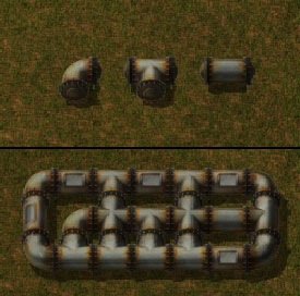
Friday Facts #260 - New fluid system

Regular reports on Factorio development.
Zavian
Smart Inserter
Smart Inserter
Posts: 1648
Joined: Thu Mar 02, 2017 2:57 am
Contact:

Re: Friday Facts #260 - New fluid system

Post by Zavian »

Responding to some quotes from the FFF.
Don’t do f**** up stuff like running in a circle indefinitely, sloshing back and forth endlessly etc.

This is expected real world behaviour to me. If you take a 0.6m diameter pipe that is 10m long and exactly horizontal and half fill it with water, then suddenly add 10 litres of water at one end then I expect that will setup a wave that will slosh back and forth until friction dissipates it. The reason you don't tend to see it in the real world is that normally such a pipe would be either not horizontal (eg a drain which has a deliberate downhill slope so water will always flow one way) or the pipe is 100% full of a fluid that is either stationary or moving at a fairly steady rate. (Look up water hammer for what can happen when a moving fluid suddenly stops in a pipe), or something like a hose where the flow of water is limited by the pressure difference between the entrance to the hose and the exit from the hose, and the friction caused by water flowing through the hose.

I can't recall a single instance of Factorio pipes doing "f**** up stuff like running in a circle indefinitely" that isn't a factory design issue that can be solved by something simple like not building a circular pipe network, using a pump to pressurise the pipe, making sure that supply equals or exceeds demand and that you aren't running into pipe throughput limits.

The same tactics also solve problems with junctions. If supply exceeds demand, (and you aren't running into pipe throughput limits) then pipes will be 100% full and the correct amount of fluid will take each branch of a junction. If supply doesn't at least equal demand, then that is a factory design issue to solve. Yes, better splitting at junctions would be nice, but in practice I've only ever seen issues when the fluid supply is insufficient either due to not enough production or pipe throughput limits. In which case better junction behaviour does nothing to address the root cause problem. (I will admit that the current junction behaviour might make people think the junction behaviour is a problem, but the root cause is not enough supply to meet demand). Note that in the Real World pipes tend to be either 100% full or something like a drain.
jcranmer
Long Handed Inserter
Posts: 90
Joined: Wed Jun 29, 2016 9:59 pm
Contact:

Re: Friday Facts #260 - New fluid system

Post by jcranmer »

GenBOOM wrote: Sun Sep 16, 2018 1:45 am I don't get why flow simulation is so hard?
Two reasons:

1. Real world fluid dynamics are actually quite complicated. To give you a flavor, here's an example I considered when I was working at a water treatment plant. The incoming raw water pumping station had 6 pumps, 4 that each could pump 60 MGD of water at full throttle and two that could only do 45 MGD. Turn all of them, and how much water gets pumped? The answer is a touch over 200MGD--there isn't enough pipe capacity to actually carry away 300MGD of water. (This also goes to show that real-world pipes in fact have a maximum throughput, indeed one that is not easy to describe with a simple number).

2. The current implementation is essentially solving equations by approximation and discretized simulation, which is noticeably slow, so everyone has their own ideas for improving it. Although, that said, all of the suggestions I've seen basically boil down to one of two options: (a) compute some sort of pressure values at each node, and transfer fluid proportional to the delta in pressure; or (b) do the same thing, but run it multiple times so that you get an analytic solution. (People arguing for a linear model analogous to electrical networks or for network flow methods are arguing for (b), since that is what you'll be doing when you actually look at how network flow and sparse linear solvers are going to work).

Incidentally, that means that the current implementation of fluids, in 0.16, is actually among the fastest ways to do it. The obvious optimization is to realize that a long pipe can be treated as a single unit (you can even do that without having to change the current fluid mechanics, since the pressure difference is linear in length). What makes pipes such UPS hogs is that their mechanics naturally incline them to do something (and a lot of something) every tick. Analytic models suffer from the issue that even a steady-state pipe isn't really a steady state; it naturally pulses fluids in and out every few ticks, so the pipe volumes are constantly changing. (The other main problem with fluid mechanics is that the update order ends up causing all sorts of weird inconsistencies).

Given the above, I'm not going to suggest my own specific fluid model. Instead, I'm going to list what I feel is important in a model:
  • Pipes should have a maximum possible throughput. Infinite flow through a pipe isn't realistic, and it doesn't feel in the spirit of Factorio.
  • If you put exactly 100 units of fluid into a pipe between a producer and a consumer, the consumer should receive exactly 100 units, not 99.9.
  • If you put exactly 100 units of fluid into a pipe between a producer and several consumers, the total value in all the consumers should be exactly 100 units; no fluid should be left in the pipe.
  • 0.001 units of fluid that prevent 100 units of fluid flowing further through a pipe shouldn't happen.
  • Fluid levels should probably be in integer or fixed point units, not floating point units.
  • I'm belaboring at this point, but I think the opportunities it opens up is important: mechanics should be sufficiently deterministic, and fluid flow sufficiently discretized and free of accumulated floating point error, that it is possible to have a fluid bus that lets you mix different fluids along it at different points of time. The 100 units go in and 99.9 units come out, or residual fluid in the pipe issues, are things which break interesting builds without really adding any value.
EraYaN
Manual Inserter
Manual Inserter
Posts: 4
Joined: Sun Sep 16, 2018 7:16 am
Contact:

Re: Friday Facts #260 - New fluid system

Post by EraYaN »

I think the Electrical network analog was the right way to go.

Just remember that a pipe is not a wire, but should be modeled as a transmission line.

https://physiology.kitware.com/Images/C ... yTable.png

They use pipe for wire, but really every pipe element should be a pipe and aperture at least, and you could add capacitive and inductive elements as well.

And tanks would work like a battery but with a flat "charge curve" with some internal resistance (modeled as a section of pipe).

And if you combine this with the element merging/ tree building, you could have really nice physical pipe dynamics. Like pumps in parallel and pumps in series would actually have different effects.
User avatar
TheYeast
Inserter
Inserter
Posts: 35
Joined: Sun Feb 05, 2017 3:57 pm
Contact:

Re: Friday Facts #260 - New fluid system

Post by TheYeast »

BlueTemplar wrote: Sat Sep 15, 2018 9:18 pm @TheYeast :
Maybe I'm mistaken, but your model sounds very similar to Factorio's current model ?
(Except that you fixed the update order issue, and want to potentially introduce a more complex pressure system / compression of fluids.)
It may very well be quite similar. I could not fully deduce what the current model is, but it's very clear to me that most of the quirks are due to the update order issue.

Now I have seen this formula pop up a number of times:

Code: Select all

Flow = (Pressure_A - Pressure_B) * 0.4 + Limited[Previous_Flow * 0.59, Target_Capacity * 0.1]
Translating this to my implementation, the 0.59 would correspond to a liquid.friction = 0.41
The 0.4 would be dt / liquid.mass.

Now to me, these values are bogus. The liquid loses 41% of its momentum every 1/60 s. Imagine throwing a ball and having it slow down by 41% sixty times a second! The only reason fluids move at all with that amount of friction is because of the gigantic acceleration under minute differences in pressure. This is expressed by the 0.4, where I would typically use just 0.01

Fluids in Factorio's current simulation seem to model a thick peanut butter paste that sticks to the pipes such that it instantly comes to a halt, but under a Jupiter-like gravity that forces it through pipes if there is any difference in level.

Sticking with the formula above, these are the values I used compared to those Factorio uses:

Code: Select all

            acceleration   momentum preservation
            
Water:      0.01	   0.999
Steam:      0.2            0.99999
Oil:        0.014          0.9

Factorio:   0.4            0.59
Water is heavy so it is slow to accelerate, and has little friction. Steam is light so it accelerates quickly under small pressure difference, and has hardly any friction at all, so it will almost instantly even out long pipes. Oil is slightly lighter than water so a little easier to speed up, but it sticks to the pipes so it slows down quite quickly. Pumps are needed to rebuild the pressure periodically when transporting it over long distances.

When the order update issue is gone, it seems to me that reasonably chosen constants like the ones above should get you any desirable fluid behaviour you want.

About the "more complex pressure system". I don't think this would really benefit the game. I just mentioned it to illustrate how reality would deal with the limited capacity of a pipe when fluids collide from two directions. In fact, the pressure would rise much more steeply than the x20 factor I used, but at a resolution 60 UPS the simulation is too inaccurate to deal with that.

So my proposal basically comes down to a two pass update to eliminate order issues, and tuning the physical constants to make the liquids behave a bit more natural. As this seems much simpler than the FFF post, I think it is worth considering.

TheYeast
csdt
Burner Inserter
Burner Inserter
Posts: 14
Joined: Mon Jan 15, 2018 1:11 pm
Contact:

Re: Friday Facts #260 - New fluid system

Post by csdt »

FasterJump wrote: Sat Sep 15, 2018 11:54 pm
csdt wrote: Sat Sep 15, 2018 10:19 pm Sources and drains:
A source would just impose a positive pressure, and a drain would be a point of zero pressure.
Although I like your model a lot, I think I disagree with this part.
Let's say you have a high pressure in your water pipes in your house. Open your faucet valve in your kitchen. The pressure inside the faucet will not drop to 0.
I think that the drains have a specific flow-rate limit, ie maximum intensity drain. This is what happens in factorio where assemblers have a maximum consumption speed.
But; let's say you have an assembler with an infinite speed, i would agree with you: the infinite sucking power would drop the pressure to 0.
That's why you need to have an internal "resistance" at both the drain and the source that would limit the maximum throughput by "adjusting" the visible pressure depending on the internal pressure, and the rest of the network.
Also, if sources would have different pressures, you would get flow from one source to the other, which is very counter intuitive and unrealistic (in practice, every source would be a valve, ie: not imposing any pressure when the actual pressure is higher).


Let me give an example. First, we need the Ohm's law equivalent for fluid: ΔP = Q * R.
Q is the flow through a pipe (equivalent to the intensity), ΔP is the pressure difference between the two ends of the pipe (equivalent to the tension), and R is the equivalent the resistance (a kind of viscosity penalty for this pipe).

Let's assume all sources have a pressure of 1 bar, and all drains have a pressure of 0.
For any component, we can compute the "resistance" to set the maximum flow when ΔP is 1 bar: R = ΔP / Q.
If we want a maximum flow of 0.5 L/s, R = 2 bar.s/L
If we want a maximum flow of 1 L/s, R = 1 bar.s/L
If we want a maximum flow of 2 L/s, R = 0.5 bar.s/L

Now, let's assume you want a source with a maximum flow of 2 L/s, a drain with a maximum flow of 1 L/s, and both are connected with a pipe that can "support" 4 L/s.

We would have:
S-R2-R4-R1-D
With S the source imposing a pressure of 1 bar, R2 = 0.5bar.s/L (internal to the source), R4 = 0.25 bar.s/L (pipe), R1 = 1 bar.s/L and D the drain imposing a pressure of 0 (the ground).

This network is equivalent to that one:
S-R-D
where R = R2 + R4 + R1 = 1.75bar.s/L
If we apply all we know about electricity networks, we would have:
Q = 0.57 L/s
the output pressure of the source (between R2 and R4): Ps = 0.71 bar
the input pressure of the drain (between R4 and R1): Pd = 0.57 bar

Now, if you say the source can have a maximum flow of 1 L/s and the drain 2 L/s, we get:
Q = 0.57 L/s
Ps = 0.43 bar
Pd = 0.29 bar

We observe exactly what you would expect: when the source produces more than what the drain consumes, the pressure in the pipe is higher than when its the opposite.

The only thing I'm unhappy with this is how the total flow decreases when the source and the drain maximum flow are close together (like in the example). But this result is physically correct, so I would say it's fine.
funky.bibimbap
Burner Inserter
Burner Inserter
Posts: 11
Joined: Sun Sep 16, 2018 9:29 am
Contact:

Re: Friday Facts #260 - New fluid system

Post by funky.bibimbap »

Hi, this is my first post and I know that I'm eight pages late, so I'm probably going to repeat what some others said before, I tried to read answers that seemed similar to mine and skipped others, I might have failed to evaluate them correctly.

First, I don't see the necessity of modelling fluids at any complex level, especially given the fact that we cannot have a pertinent visual feedback to see what is happening. Beyond that, I don't see where the fun would be to try and compute best solutions for complex pipe networks with complex models of fluids. And then there's the elephant in the room: what is powering my conveyor belts in the first place? Please don't make the game realistic for the sake of being realistic, because it is not!

So obviously I'm all for the "nuclear option", which is simplifying as much as possible.

This implies using some graph theory and discrete maths with the following characteristics (I use the oil example here):
  • A well is a source
  • A refinery is a sink
  • Pipe intersections are vertices
  • Tanks discussed right after
  • A pump is a sink in one graph and a source in another (if both sides of the pump connect to the same graph, the pump is just a pipe)
  • A valve is a new component that allows one direction travel for fluids, it is a sink
  • Stretches of non-intersecting pipes are edges
  • Fluids travel instantly through the network, but can be stored in the pipes
  • Everything relies on the maximum flow of the pipe network
The question of the maximum flow for the graph is solved by finding its (or one of its) minimum cut. That has been studied for a very long time, there are lots of solutions out there. And a further simplification is then introduced: let's ignore the actual well's output, let's just consider that each edge has a weight of 1. So I have 4 wells, 5 refineries, and I compute that the mincut is 3, this means that no matter what, my refineries cannot receive more that three times the capacity of a pipe. Let's say a pipe has a capacity of 100, the maximum flow is 300. And we split evenly between the sinks, so each refinery can receive 300/5 units at each tick. The valves would be lower priority sinks, and receive whatever the refineries did not consume (and then share it amongst themselves).

So, how is the fluid stored? We just consider that the pipe network is a single piece of storage. The amount of fluid pumped into the network and not consumed (either because of the maximum flow limit, or by lack of consumption by refineries) is added to the network's storage. On the other hand, when the refineries consume more than the pumps can provide, the necessary amount of fluid is removed from the network's storage, but (and it is important) while still respecting the maximum flow limit.

Now storage tanks can be connected in two different ways: directly by a pipe, in which case they just increase the pipe network's capacity, or through pumps and valves, in which case they become separate networks. Either way, the total amount of fluid they contain is a weighted average of the network's storage level.

As an added bonus, it is now very easy to show on-screen the different networks, and their minimum cuts.
Escadin
Fast Inserter
Fast Inserter
Posts: 181
Joined: Thu Mar 17, 2016 3:15 pm
Contact:

Re: Friday Facts #260 - New fluid system

Post by Escadin »

This FF get me thinking.

First of all, why don't you throttle the max throughput of a segment by a factor proprotional to it's length? Is that not supposed to be a thing anymore? Then what are pumps good for?


And then what speaks againt a more naive approach?
Instead of calculating fluid behaviour every tick I'd calculate and the define the pipes as a directed network, then move an amount of fluid according to the weight of each segment. Direction is determined by sinks and sources, weight is remaining max throughput of the segments (also capped by wthroughput of previous segment).
In case of junctions or when there isn't enough fluid to maxout throughput each segment gets a proportional split.

The network is only recalculated when something changes (pipe added / removed).

While, yes this is just a naive approach I wonder what would be wrong with it?
"--? How are commands compounded in a compounded compound command commanding compound composts." -defines.lua
User avatar
TheYeast
Inserter
Inserter
Posts: 35
Joined: Sun Feb 05, 2017 3:57 pm
Contact:

Re: Friday Facts #260 - New fluid system

Post by TheYeast »

Escadin wrote: Sun Sep 16, 2018 11:07 am First of all, why don't you throttle the max throughput of a segment by a factor proprotional to it's length?
Yes, I proposed the same thing above. This would make the optimisation less apparent. Without this a long segment would allow 'teleporting' fluid over a long distance at zero cost in throughput.
Escadin wrote: Sun Sep 16, 2018 11:07 am Instead of calculating fluid behaviour every tick I'd calculate and the define the pipes as a directed network, then move an amount of fluid according to the weight of each segment. Direction is determined by sinks and sources [...] The network is only recalculated when something changes (pipe added / removed).
I don't think it is that easy. Supply and demand are pretty erratic. Refineries produce fluid in batches, and chemical plants consume in batches as well. Even if you would try to make this more smooth over time, when a product output becomes clogged, input demand will suddenly drop as well. Fluids in pipes to Storage tanks will often reverse direction to compensate for sudden shortage or surplus.

But as I outlined in my earlier post, I think there is indeed a simple approach that is computationally cheap (at least compared to belts and inserters) and solves the problems mentioned in the FFF.
pattyboy27
Manual Inserter
Manual Inserter
Posts: 1
Joined: Sun Sep 16, 2018 1:43 pm
Contact:

Re: Friday Facts #260 - New fluid system

Post by pattyboy27 »

Matthias_Wlkp wrote: Fri Sep 14, 2018 11:47 pm I'm reading these suggestions and I find this all way too complicated.

How about something REALLY simple:

1. Treat all connected pipes like a single storage tank.
2. Each pipe adds to total volume.
3. Measure two parameters of a single system - total volume and fill ratio (% of how much of it is full).
4. Any entity loading fluid into the system cares only if there is free space and adds instantly.
5. Any entity taking from the system has defined, how much fluid it can take per tick - say X
- per tick, take X * fill ratio - this way it would take more if the pipe is full and would gradually slow down until it balances itself if there is insufficient fluid stream
6. To avoid a situation when multiple machines take more fluid than there is in the system you have a couple of options:
a) don't allow the entities to take any fluid if there is less than Z% of the pipe full, assuming that X * 3 * Z% is less than volume of a single pipe
b) gameplay over physics - let the entities take more fluid than there is, forcing volume below zero, after 1 tick resupply to "0". Nobody (sane) will notice or care for a tiny surplus of a fluid for one tick...

Solves all your issues:
- tick effective (1 entity to calculate per chain of any pipes)
- splits fluids evenly
- allows for clearing a fluid type from a pipe system (with 6b)

Downsides - described in pt. 6.

Go simple!


(I am posting this without having red any further, so it might have already been responded to - but oh well)

This was pretty much my thought when I was reading along, but your post is much more developed than I had gotten to yet. It's probably too close to the nuclear option?
Blacky007
Fast Inserter
Fast Inserter
Posts: 180
Joined: Fri Dec 29, 2017 8:05 pm
Contact:

Re: Friday Facts #260 - New fluid system

Post by Blacky007 »

one thing from current system I have seen is that if you have 3 full tanks and a pump after it, at a 4-juntion the tanks are emptied clockwise?
the are not getting reduced at the same value - only one after the next ???
My color birthday was May 2nd 2020 - Thank you Enchroma
Avezo
Filter Inserter
Filter Inserter
Posts: 454
Joined: Fri Apr 01, 2016 3:53 pm
Contact:

Re: Friday Facts #260 - New fluid system

Post by Avezo »

As a test case for whatever final solution to this matter comes, check the issue I'm having with (what it seems) weird turbine fluidbox update order in my nuclear setup:
viewtopic.php?f=18&t=62516&p=379082#p379082
Bizz Keryear
Long Handed Inserter
Posts: 91
Joined: Thu Oct 22, 2015 5:08 am
Contact:

Re: Friday Facts #260 - New fluid system

Post by Bizz Keryear »

I am starting at one of your last points:
Perhaps refactor it from floats to integers, which would make it work more cleanly, but would also make some calculations more complicated. TBD.
You can avoid some of your troubles by simply rounding your results. A tank with 0.1 in it then would simply be empty.

Anyway, I hope with your improvement I finally can run two pipes in parallel which are connected to each other to double the throughput without running in trouble like I did in the past (had to learn that this doesn't work in Factorio)

Unrelated sidenote: I also hope that the saving mechanism finally becomes a background task before release. It is still one of the things that bothers me most.
User avatar
Tesse11ation
Fast Inserter
Fast Inserter
Posts: 186
Joined: Sat Mar 05, 2016 12:59 am
Contact:

Re: Friday Facts #260 - New fluid system

Post by Tesse11ation »

Drury wrote: Fri Sep 14, 2018 2:29 pm Here's a fun challenge for you:

No power network allowed. If two poles make a wire connection, you have to disconnect them with shift-click. The result is that instead of an electricity network, you now have a sprawling steam pipe network with steam engines and turbines all over your factory. It's much less masochistic than it sounds, trust me. It forces some creative designs and introduces fluid throughput woes as your factory grows (and you'll have to be running steam trains to outposts, yay). Also, steam panels become much less OP and kinda useful for circuit applications.
Ok, that just sounds awesome. I kinda want to try this now.

One thing I wonder is if steam temperature data is preserved when it gets loaded onto a train. This is actually really important because of how much hotter steam from heat exchangers runs compared to boilers, and the potential difference with steam engines vs. turbines.
ImageImage
System Specs
OS: Windows 10 Professional 64 Bit
CPU: AMD Ryzen 5 3600X (@~3.8 gHz)
GPU: Nvidia RTX 2080
RAM: 32GB DDR4 (2400)
DRIVES: 2x 1TB NVMe SSD, 1x 6TB HDD
User avatar
Tesse11ation
Fast Inserter
Fast Inserter
Posts: 186
Joined: Sat Mar 05, 2016 12:59 am
Contact:

Re: Friday Facts #260 - New fluid system

Post by Tesse11ation »

bobingabout wrote: Fri Sep 14, 2018 4:44 pm Actually, reading a few of these posts, I had a question.
what about "pipe" based entities (in this case, it's a storage tank) that have an input connection and an output connection that are basically just a pipe to force a flow direction?
Metuk wrote: Fri Sep 14, 2018 3:11 pm
bobingabout wrote: Fri Sep 14, 2018 2:55 pm 1. You didn't let me write my contribution to the FFF.
I'm interested - what was your contribution to this FFF?
I've been working on this for 2 weeks, so I'll post a screenshot.
https://www.dropbox.com/s/exwhtp1c3qgaa ... 9.png?dl=0
note: for testing reasons and it's easy to obtain nature, I gave water a fuel_value, so think of it as some kind of "Fuel" oil in everything except the boiler's normal water input.
Also, this is a feature I wrote for modding, it is unlikely (if it even makes it into the game engine) that anything in vanilla will use this feature.
Also, this is actually 2 separate features. "Fluid energy source" and "reactor dynamic energy source", I just used the first feature with the second to make a reactor powered by "oil", then another powered by "steam"

Not pictured here is also a steam powered boiler, because Klonan dared me to do it. That's in another screenshot. Yes, it is as dumb as it sounds.
Holy crap, that's great. I'd love to see that steam powered boiler. I'm a sucker for stupid cheesy shit.
ImageImage
System Specs
OS: Windows 10 Professional 64 Bit
CPU: AMD Ryzen 5 3600X (@~3.8 gHz)
GPU: Nvidia RTX 2080
RAM: 32GB DDR4 (2400)
DRIVES: 2x 1TB NVMe SSD, 1x 6TB HDD
User avatar
Tesse11ation
Fast Inserter
Fast Inserter
Posts: 186
Joined: Sat Mar 05, 2016 12:59 am
Contact:

Re: Friday Facts #260 - New fluid system

Post by Tesse11ation »

Ghoulish wrote: Fri Sep 14, 2018 6:38 pm Interesting FFF! Great write up.
Dominik wrote: Fri Sep 14, 2018 6:18 pm We are still considering using different pipes for different shapes, which would allow two parallel separate pipes etc.
Please do add this feature, flow control is a mod which adds these and it truly does improve fluid handling, especially in the later part of the game where the pipework turns in to the proverbial spaghetti. We've all been there - you need to sneak a pipe through a gap but can't because it'll connect to the pipe next to it and different fluids would mix..

Image
Ok, this is all well and good, but I feel it's pertinent to include one minor detail that will be a HUGE QoL feature for literally everyone.

Rather than having different types of pipes for everything, stick with just the basic pipe and underground pipe... BUT, when holding a regular pipe, you can rotate them just like belts to produce different junctions and directions. The default pipe "rotation" can actually be the 4-way pipes that we essentially have all the time now, so that people like me who are used to the current system aren't wildly rotating pipes to find the 4-way one.
ImageImage
System Specs
OS: Windows 10 Professional 64 Bit
CPU: AMD Ryzen 5 3600X (@~3.8 gHz)
GPU: Nvidia RTX 2080
RAM: 32GB DDR4 (2400)
DRIVES: 2x 1TB NVMe SSD, 1x 6TB HDD
leoch
Fast Inserter
Fast Inserter
Posts: 136
Joined: Fri Dec 16, 2016 9:37 pm
Contact:

Re: Friday Facts #260 - New fluid system

Post by leoch »

Alternative to above ↑ for flow control:

- standard pipes can only form two connections, i.e. straight or corner
- a new piece, pipe hub, can form up to 4 connections

Also, please consider dedicated graphics for diagonal pipes as with rails (and maybe even a pipe planner).
Dominik
Former Staff
Former Staff
Posts: 658
Joined: Sat Oct 12, 2013 9:08 am
Contact:

Re: Friday Facts #260 - New fluid system

Post by Dominik »

TheYeast wrote: Sat Sep 15, 2018 8:47 pm Physicist here. I happened to bring up the wonky fluid behaviour about a year ago, but it didn’t seem to be a high priority at the time. Back then I came up with some alternative algorithms and ran some simulations in an Android app I hacked together for this purpose (can send APK+source if interested).

Based on what I came up with, the proposed model seems needlessly complicated to me. So I think my findings are worth sharing.

In my simulation I used the Euler equations (assumes zero viscosity) because they are computationally cheap and good enough for our purpose.
...
Hi Yeast,
thanks you for your proposal, so far it seems to be the most reasonable, although I am still unsure about the electricity model which also is interesting.
I admit that my knowledge of physics is rather limited, I had to rely on my common sense. About the “speed kinda models the pressure”, I suppose I could have put more thought into it when writing it. When I think about it, pressure describes it best, it's just that it developed from speed originally and is still called that and I never took the time to rethink what it is.
The model actually is not that dissimilar. The pipe segment has volume (same to level), and the pressure, and connections store the speed - which is just the last step flow. The speed only plays some role in the update and does not control it fully.
From what you propose I really like the idea to push towards only using the last state. I will have to think about it, might steal it. Right now I am thinking about allowing going over the pipe volume limit which would allow this and simplify things a lot.
Your equations are a simplified version of what I currently have. Unfortunately I don't think it would work very well in this form.
The main issue I see is a very low reaction speed. For example - have a straight pipe from source to drain, source is pumping, drain is closed, pipe is full. The drain opens. What I think your model does is that in first tick, only the last segments moves 1/4 of its fluid into the drain (assuming dt=1, which is about what we have) and all the rest stays in place. In next step, one more segments moves a bit, 1/16. Etc. You need "length of pipe" iterations for the wave to reach the source and quite many more to get speed. And then when you get the momentum and you close the pipe, how does the flow stop?
Even so, your ideas are inspiring, I think I will use them, if you don't mind :)
Thank you, D.
pleegwat
Filter Inserter
Filter Inserter
Posts: 278
Joined: Fri May 19, 2017 7:31 pm
Contact:

Re: Friday Facts #260 - New fluid system

Post by pleegwat »

Dominik wrote: Sun Sep 16, 2018 7:18 pm The main issue I see is a very low reaction speed.
That's a real thing; If I remember correctly it's related to the speed of sound in the liquid. Looking at the nearest neighbours on the previous tick gives you a speed of 60 tiles per second. Google gives me real speeds of 1000-1500 m/s for common fluids however.

To allow for a faster propagation you'd need either to look at connected segments up to about 20 tiles away, or run about 20 simulation steps per tick, or some combination of the two. Which will probably not be a nice thing for performance particularly in many-junction environments.

I'm sure a physicist will be along shortly to tell me how wrong I am.
NexGenration
Burner Inserter
Burner Inserter
Posts: 15
Joined: Fri Apr 27, 2018 9:26 pm
Contact:

Re: Friday Facts #260 - New fluid system

Post by NexGenration »

So will these changes fix the fact that you practically need a pump literally every 3 pipes just to get enough fluid throughput to feed large fully beaconed setups? I'm currently designing a mega base sized oil processing factory and dealing with putting enough pumps in is just a nightmare. There's no way to avoid the massive amounts of pipe spaghetti.
User avatar
Nova
Filter Inserter
Filter Inserter
Posts: 959
Joined: Mon Mar 04, 2013 12:13 am
Contact:

Re: Friday Facts #260 - New fluid system

Post by Nova »

These conversations are nice. especially TheYeast's post was interesting to read. No idea if it really is scientific accurate, but it sounds coherent.
Post Reply

Return to “News”