In my modded factorio map I often found myself in a situation where I'd need to connect mutiple places with one wire but still have the signals in it be separated. For example: Multiple iron mining outposts transmitting the amount of ore left back to base - all of them send an iron ore signal with an amount. In this case they'd just all sum up and I wouldn't know which one's which.
That's why I came up with:
Logic Wire Network
disclaimer
I'm using my own modified vesion of the Alphabet mod originally made by DaCyclops here (if you have any problems with it please let me know).
It just adds a couple more colored signals to make my life easier though that means that I'll be using them here.
I'll attach the mod to this post
It just adds a couple more colored signals to make my life easier though that means that I'll be using them here.
I'll attach the mod to this post
Version 1.0
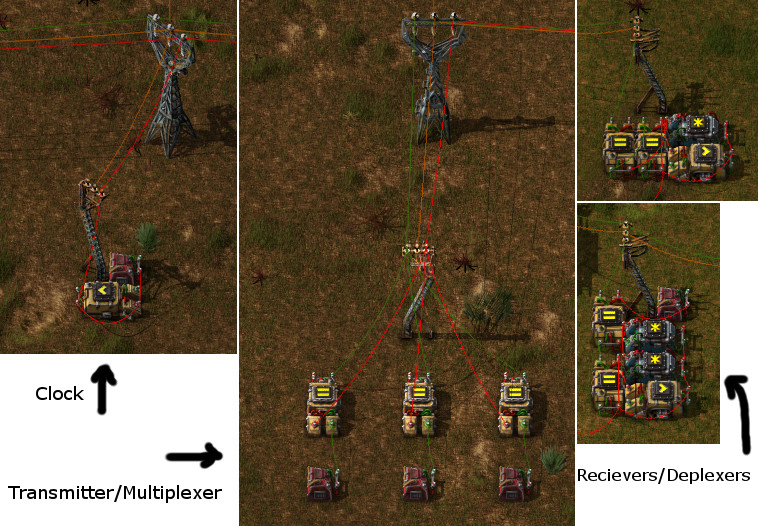
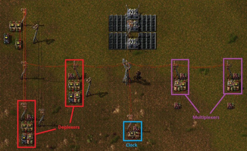
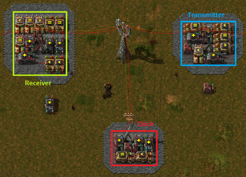
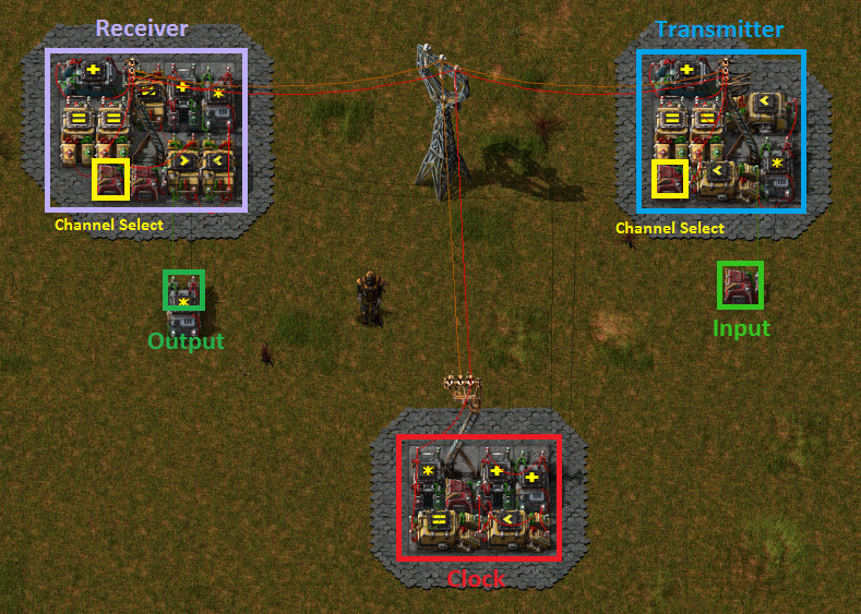
Basically - everything is connected via a 'common bus' (red wire) on which multiple 'channels' exist. It is like running mutiple wires in parallel just way simplier. You can then hook up to it using a transmitter or a reciever.
The system consists of three main elements:
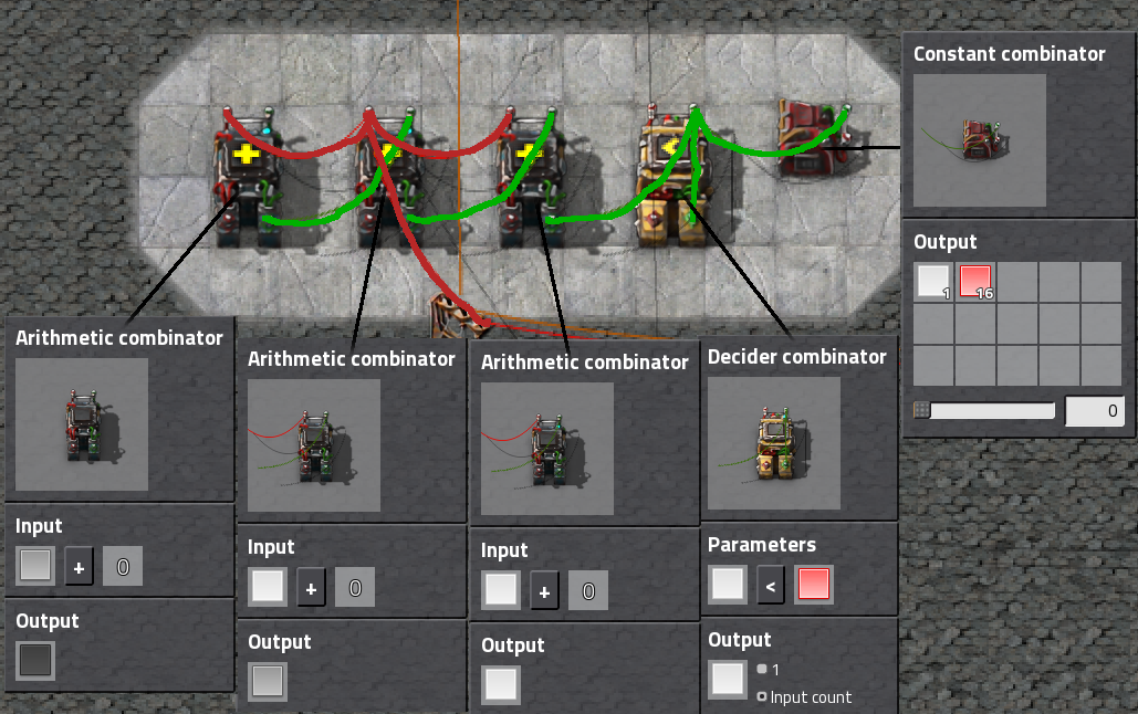
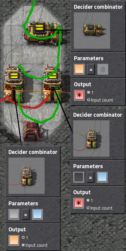
The Main Clock
This is the thing that makes sure all the signals are synced up.
compacted:
How to use:
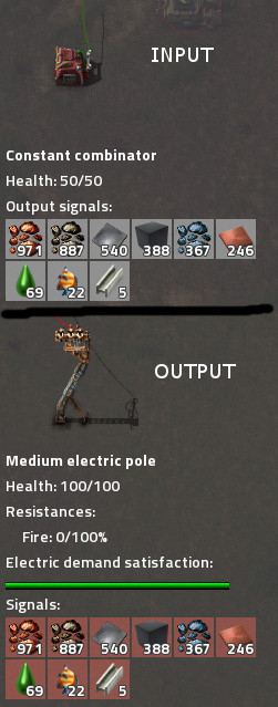
Connect the red wire to the network and in the constant combinator set the red signal to the amount of channels you want to use (channel 0 doesn't exist but the number you set does, also note that the more channels the longer the raction time will be - with 60 channels it would be 1s)
How it works:
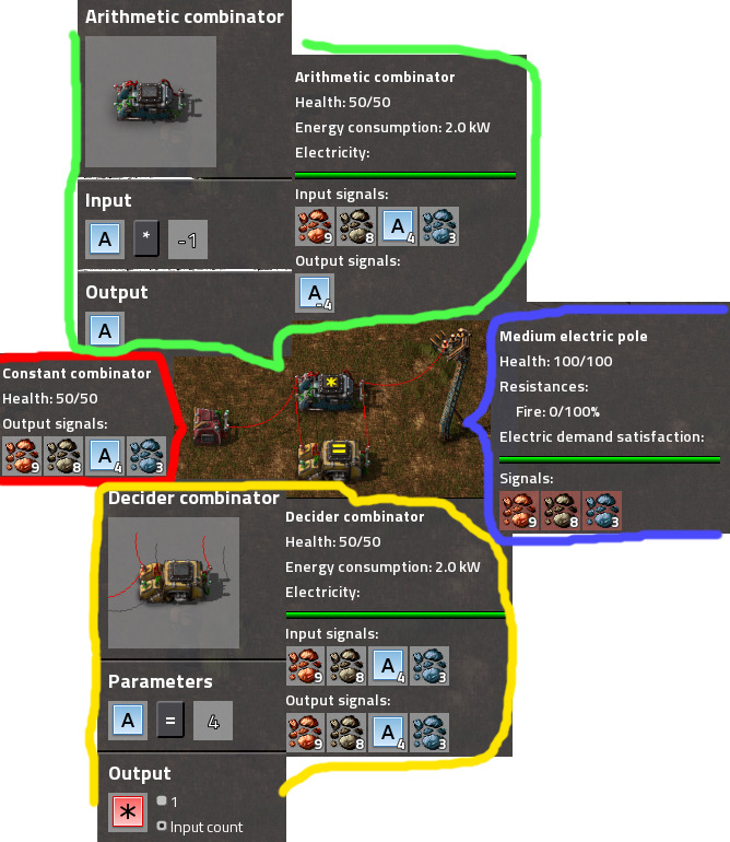
It's basically a regular clock (the constant and decider combinator).
It's output then goes through the cascade of three arithmetic combinators which do the following:
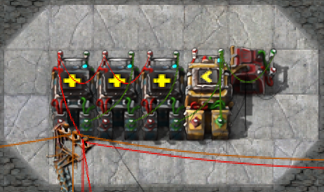
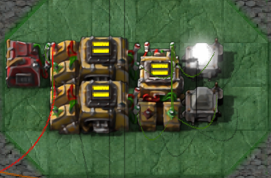
Transmitter
This one is used to send signals to the network on a specified channel.
compacted:
How to use:
Connect the red wire to the network and in the right combinator (the one that is outputting purple to the green wire) set the number to the channel you want to send to. The constant combinator only represents the signal source - attach this wire to your smart chest or whatever instead.
How it works:
This is the simpliest part of the system. It has an input combinator which sends a purple signal to the 'local network' (green wire) when white signal has the value of the desired channel. Then there is the output combinator which sends everything to the common bus when purple is 1. Because the value of white only stays the same for 1 tick the signals on the bus are there also only for one tick.
An important thing to notice is that there are two combinators in series between the input (particular white value on common bus) and output (everything from the local network to the common bus). That means that there's 2 tick delay. Conveniently the black signal is delayed 2 ticks after white so the correct value of black is going to be on the common bus at the same time as the contents just sent. That's used in the reciever.
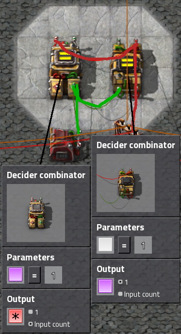
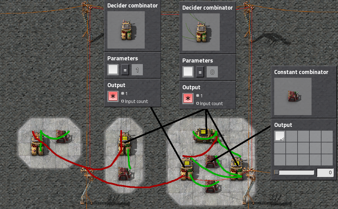
Reciever
This one is used to read the signal from a specified channel in the network.
compacted (don't mind the lamps, they're there just for testing):
How to use:
Connect the red wire to the network and in the constant combinator set the blue signal to the number of the channel you want to use. Then connect your output to the green wire on the top (you can connect a red wire too but you will get some flickering by doing that).
How it works:
This one is quite complicated... It has two inputs from the common bus and one output to local network.
The 'odd' combinator (output everything when orange = 0) is the buffer. It makes the signals stay on when they're not on the common bus - pretty much like a simple memory.
There is one little problem here: If you want to use the local network not only for reading and using the signals from the common bus, you have to make sure that you put some kind of combinator to streamline the signals out of the buffer (anything > 0 output everything or something like that). Otherwise you'll see weird things happening - namely the buffer trying to save the signals coming from anywhere else then itself (mayhem ).
).
The first input (grey in from common bus, orange out) is the reset combinator. It makes sure that the buffer is reset just at the right time to prevent doubling the signals on the output but also 'flickering' (signals disappearing for a while).
The second input is the data input. When black is the correct value it sends the contents of the common bus to the buffer. This will happen one tick after resetting it which means that when there is the 1 tick when the buffer is empty before it fills up, the signals are provided from the common bus. That means that there is no output 'gap' or 'flicker' since the data input is also connected straight to the output and then, on the next tick when the data input signal is gone, the buffer has it's content back in place.
I might add my control center with configurable nixie tube display when I have the time.
signal time table
This table shows what happens when the channel condition is met on the main bus.
The situation is following:
Eventhough this system is in my eyes flawless it does have some limitations:
The system consists of three main elements:
The Main Clock
This is the thing that makes sure all the signals are synced up.
compacted:
How to use:
Connect the red wire to the network and in the constant combinator set the red signal to the amount of channels you want to use (channel 0 doesn't exist but the number you set does, also note that the more channels the longer the raction time will be - with 60 channels it would be 1s)
How it works:
It's basically a regular clock (the constant and decider combinator).
It's output then goes through the cascade of three arithmetic combinators which do the following:
- convert the signals to the respective colors
- make them timed properly
- white - send signal: The transmitter sends it's signals
- grey - reset signal: The reciever resets the content of it's buffer
- black - read signal: The reciever reads the status of the common bus (red wire)
Transmitter
This one is used to send signals to the network on a specified channel.
compacted:
How to use:
Connect the red wire to the network and in the right combinator (the one that is outputting purple to the green wire) set the number to the channel you want to send to. The constant combinator only represents the signal source - attach this wire to your smart chest or whatever instead.
How it works:
This is the simpliest part of the system. It has an input combinator which sends a purple signal to the 'local network' (green wire) when white signal has the value of the desired channel. Then there is the output combinator which sends everything to the common bus when purple is 1. Because the value of white only stays the same for 1 tick the signals on the bus are there also only for one tick.
An important thing to notice is that there are two combinators in series between the input (particular white value on common bus) and output (everything from the local network to the common bus). That means that there's 2 tick delay. Conveniently the black signal is delayed 2 ticks after white so the correct value of black is going to be on the common bus at the same time as the contents just sent. That's used in the reciever.
Reciever
This one is used to read the signal from a specified channel in the network.
compacted (don't mind the lamps, they're there just for testing):
How to use:
Connect the red wire to the network and in the constant combinator set the blue signal to the number of the channel you want to use. Then connect your output to the green wire on the top (you can connect a red wire too but you will get some flickering by doing that).
How it works:
This one is quite complicated... It has two inputs from the common bus and one output to local network.
The 'odd' combinator (output everything when orange = 0) is the buffer. It makes the signals stay on when they're not on the common bus - pretty much like a simple memory.
There is one little problem here: If you want to use the local network not only for reading and using the signals from the common bus, you have to make sure that you put some kind of combinator to streamline the signals out of the buffer (anything > 0 output everything or something like that). Otherwise you'll see weird things happening - namely the buffer trying to save the signals coming from anywhere else then itself (mayhem
The first input (grey in from common bus, orange out) is the reset combinator. It makes sure that the buffer is reset just at the right time to prevent doubling the signals on the output but also 'flickering' (signals disappearing for a while).
The second input is the data input. When black is the correct value it sends the contents of the common bus to the buffer. This will happen one tick after resetting it which means that when there is the 1 tick when the buffer is empty before it fills up, the signals are provided from the common bus. That means that there is no output 'gap' or 'flicker' since the data input is also connected straight to the output and then, on the next tick when the data input signal is gone, the buffer has it's content back in place.
I might add my control center with configurable nixie tube display when I have the time.
signal time table
This table shows what happens when the channel condition is met on the main bus.
The situation is following:
- the signal count is 16
- the shown transmitter and reciever are set to channel 1
- send in - transmitter combinator in
- send out - transmitter combinator out
- recive reset - reciever reset combinator
- recieve data in - reciever data input combinator
- recieve buffer - reciever buffer
Code: Select all
tick_#_|_white_|_grey_|_black_|_send_in______|_send_out_____________|_recieve_reset_|_recieve_data_in______|_recieve_buffer_______|
0      | 16    | 15   | 14    | 0 - 0        | 0 - 0                | 0 - 0         | 0 - 0                | 1 - in.c. everything |
1      | 01    | 16   | 15    | 1 - 0        | 0 - 0                | 0 - 0         | 0 - 0                | 1 - in.c. everything |
2      | 02    | 01   | 16    | 0 - 1 purple | 1 - 0                | 1 - 0         | 0 - 0                | 1 - in.c. everything |
3      | 03    | 02   | 01    | 0 - 0        | 0 - in.c. everything | 0 - 1 orange  | 1 - 0                | 0 - in.c. everything |
4      | 04    | 03   | 02    | 0 - 0        | 0 - 0                | 0 - 0         | 0 - in.c. everything | 1 - 0                |
5      | 05    | 04   | 03    | 0 - 0        | 0 - 0                | 0 - 0         | 0 - 0                | 1 - in.c. everything |
- you can't use the signals used in the setup (I intentionally didn't use red green and yellow since they're the most common in my setups, also that's why I use the modified Alphabet mod)
- you can't use the reciever with other things outputting signals on the same wire (this can be solved by making the signals go only in one direction - decider combinator if anything > 0 then output everything - or something like that)
- with lots of channels it gets quite slow (though I can't imagine any use with more then like 300 channels - that is 5s delay)
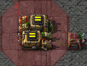
version 2.0
Version 2.1This is what I came up with in reaction to Dr. Walrus' design posted bellow. It only uses a single signal and outputs 'clean' signals.
The clock is pretty much the same as in v1.0 (except the missing arithmetic combinators of course) and the rest of the constants are the channel selection ones. You have to specify the channels as negative numbers in v2.0 so keep that in mind!
For other details please see 1.0 above or my post somewhere in here (didn't have too much time to waste typing this...).
The brand new almost perfect design featuring:
- Channel selection as positive numbers (thanks to Dr. Walrus)
- No 'channel overlap' as in 2.0
- Just one signal used
- 'Clean' output
All other details remain unchanged...
Except it has one tick longer delay but who cares?
picture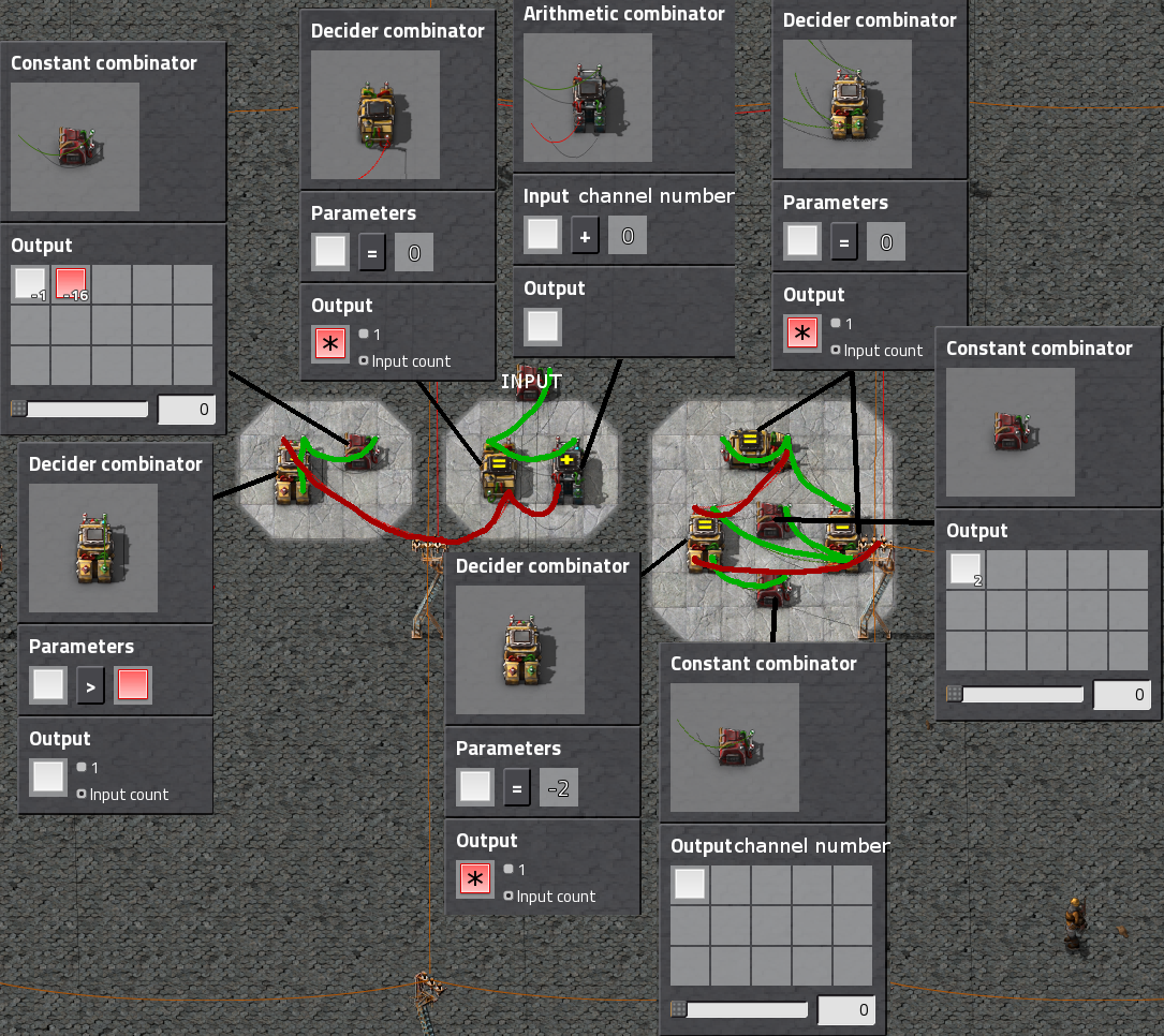
Let me know what you think