Small problem... If you are using ANY signal you should specify output signal type, and without correct type you won't be able to sum signal with opposite memory cell. Am I missing something?DaveMcW wrote: That is pretty easy.
Set up 2 memory cells, 1 with all signals, 1 with all negative signals (each * -1).
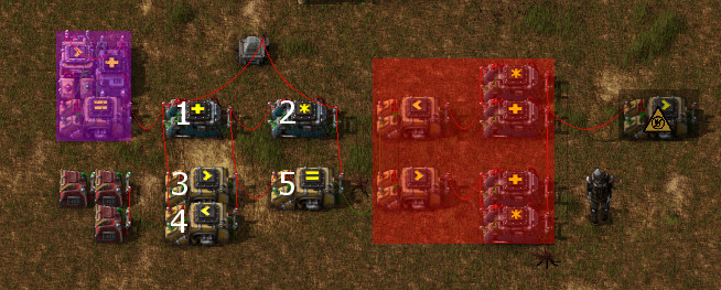
Each tick, use the ANY signal to pick one signal from each memory cell. Then feed it to the opposite memory cell to delete it. Also feed it to the opposite ANY combinator to avoid any delays.
- 1.png (246.05 KiB) Viewed 31507 times
That's why this is a challenge.Dr. Walrus wrote: Getting it down to one tick between each output might be hard but not impossible.
Yep.Dr. Walrus wrote: Also would the signals all be positive?