0.15.11 heat pipes

Post all other topics which do not belong to any other category.
Post Reply
vanatteveldt
Filter Inserter
Filter Inserter
Posts: 946
Joined: Wed Nov 25, 2015 11:44 am
Contact:

0.15.11 heat pipes

Post by vanatteveldt »

OK, so they nerfed heat pipes... My power plant suddenly just about halved capacity. How to we design a new plant? It seems that we need to minimize distance between power plant and heat exchangers. There's probably smart people who can figure out the math, but I'm just a poor social scientist so I do things experimentally.

I like building my heat exchangers in blocks of 16 since your first two reactors feed 16 exchangers, and after that every pair of reactors feeds another 32 exchangers (source: https://www.reddit.com/r/factorio/comme ... ar_ratios/)

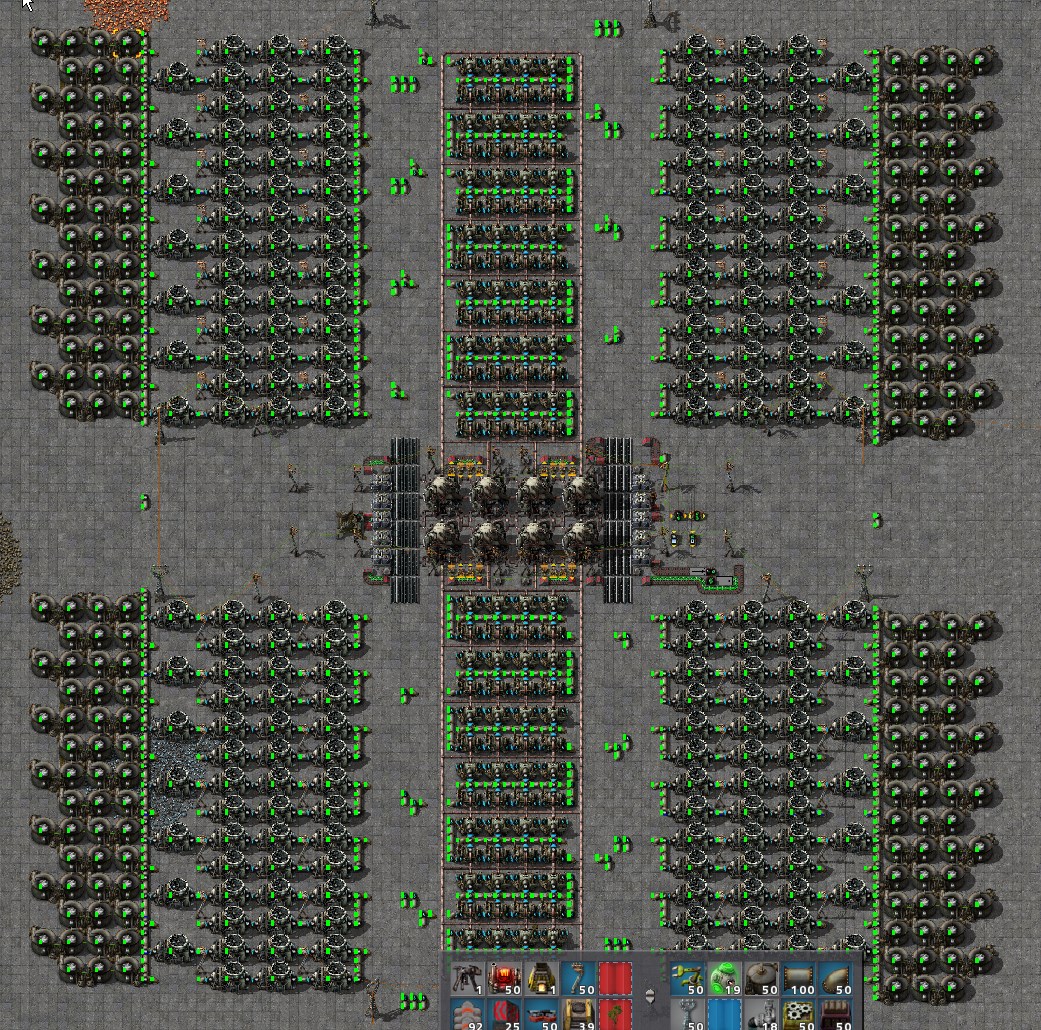
My naive design was to have a column of heat exchangers followed by two columns of turbines and a column of storage tanks. This worked wonders, but now have such large blocks near the reactor will make it difficult to stay within the limit of the heat pipe.

From what I can see, 16 exchangers under full load can be serviced up till 65 heat pipes distance. Since the column itself takes 16*3=48 pipes, this gives you only 17 pipes to connect to the reactor. If you have a 4x2 design which needs 7x16 exchangers there is no way it will fit all within 17 tiles of the reactor (right?)

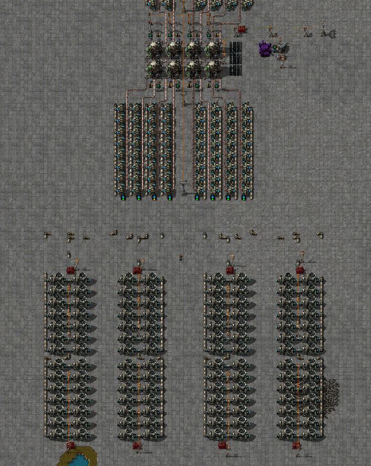
The solution is probably to separate heat exchangers from turbines. Apparently an exchanger produces about 103 steam/s (https://www.reddit.com/r/factorio/comme ... s/dgv04zb/). If .14 lore is still correct, a pipe can transport 900/s over longish distances and 1200/s over shortish distances (<14 tiles, where UG pipes count as 2 tiles?). So, the steam from 16 exchangers can be safely transported over long distances by 2 pipes.

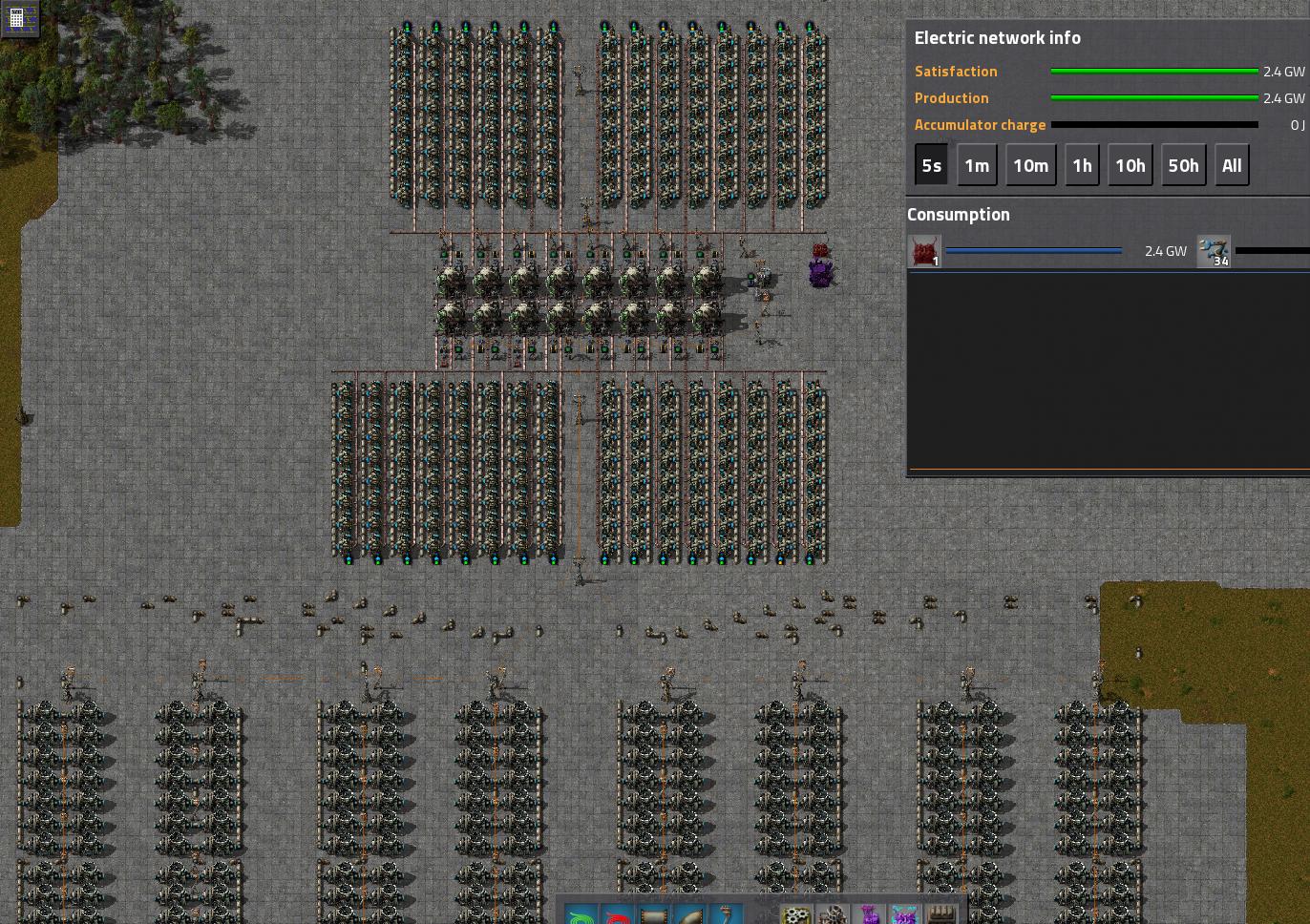
This is confirmed by the fact that this setup produces maximum expected power of 160MW:

Image

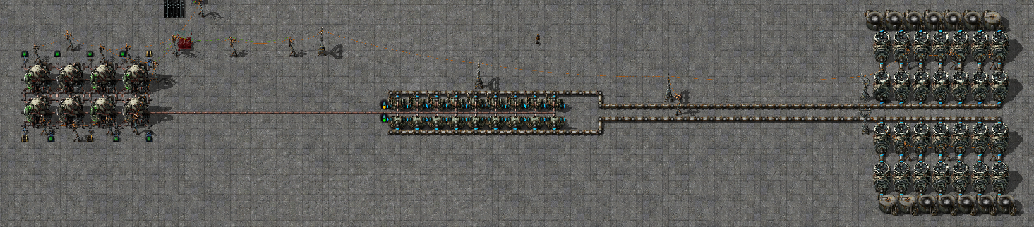
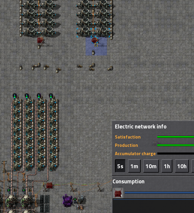
If you move the exchangers 2 tiles away from the reactor, performance drops to 140MW, apparently the 62 pipes now between reactor and furthest exchangers is about the limit.


Steam, however, we can move pretty far away, especially with the new pumps (is there a post explaining .15 liquid throughput and pumps?). Obviously you can use underground pipes to further increase allowed distance, but if the wiki is still correct you get 90/s throughput until 224 pipes, so that should be enough for most purposes.

So, I think reactor design will now have three concentric rings: reactor core >-heat pipes -> heat exchangers >- steam pipes -> turbines.

I guess that also makes it attractive to think in terms of 1 pump : 8 exchangers : 14 turbines. This puts less strain on a single heat pipe, allowing you (experimental value) 91 tiles between reactor and furthest turbine, or about 65 tiles before the start of a row of 8 turbines. Since adding a block of 2 new reactor cores requires 4x8 extra exchangers and gives more than 4 connection points for heat pipes, it seems that this should allow you to build out more or less arbitrary.

User avatar
TruePikachu
Filter Inserter
Filter Inserter
Posts: 978
Joined: Sat Apr 09, 2016 8:39 pm
Contact:

Re: 0.15.11 heat pipes

Post by TruePikachu »

It might also be possible to situate the turbines even farther, if you feed from boilers into tanks and then directly into a pump (with no pipes between the pump input and the tank). If you need more than one pump of throughput, just use multiple tanks and pumps in parallel :)

iceman_1212
Filter Inserter
Filter Inserter
Posts: 256
Joined: Wed Aug 17, 2016 9:49 am
Contact:

Re: 0.15.11 heat pipes

Post by iceman_1212 »

hey van - here is an 8-reactor, zero-waste setup with independently powered "controller" (i.e., inserters, combinators) that is verified to output very close to theoretical max of 1120MW in 15.11. you can see in the save file that it shows stable performance over time when a load of 3733 radar are placed which have a draw of 1119.9 MW. (i tried using passive electric void initially but power window has too few significant figures for that to be useful). the stuff in the middle that is monitoring steam levels and inserting / removing fuel cells is intentionally on separate power network so as to not run into bad values in the combinators in event of power overdraw. the #s of off-shore pumps are higher than optimal #s for the sake of conservatism - i budget only 800 per second in each of the water/steam lines. there are also a couple more storage tanks than absolute minimum # required because system was more stable.

it is on purpose that it is a simple belt / inserter mechanism that controls the fuel cell feed (excluding the radar which i included for global map view monitoring, the controller should take ~224kw to operate, 12 yellow inserters and 4 combinators). in the event of a brown out, restarting this system is trivial - just need to get fuel cells onto the belt. (in contrast to logistic bot based systems which are themselves very energy hungry, in comparison.)

i send steam from heat exchangers to turbines to tanks, which is what you're doing as well, from the looks of it. i see a lot of setups sending steam from heat exchangers to tanks to turbines but that seems to be throughput limited (and not nearly as stable) at high loads and low steam levels unless many pumps are spammed

anyways, sorry for the quick / not-so-good description but it is turning out to be a busy day on my end - have to head back into office shortly :(

the bp string exceeds maximum # of allowed characters in a post :lol: so here is the save file instead. hope it helps - lmk if you have any questions.

i suspect it will probably be difficult to arrive at min-max (or close to it) for this one using empirical testing only since bottlenecks with heat transfer/flow aren't readily apparent visually unlike with belts/assemblers/oil plants.

p.s. us non-engineers gotta stick together 8-)

save file with nuclear test setup, i had creative mode enabled but didn't use it. vanilla should work fine: https://www.dropbox.com/s/kwebplrupcav3 ... r.zip?dl=0

Image

Mehve
Filter Inserter
Filter Inserter
Posts: 318
Joined: Sat Aug 06, 2016 9:12 pm
Contact:

Re: 0.15.11 heat pipes

Post by Mehve »

Yeah, this is definitely going to take some redesigning for big assemblies. I haven't had time to do some in-depth testing, but there's definitely benefit to running multiple pathways when it comes to getting maximum work out of each heat exchanger. But heat pipes are pricy little buggers before endgame, so I think that'll be a last resort.

vanatteveldt
Filter Inserter
Filter Inserter
Posts: 946
Joined: Wed Nov 25, 2015 11:44 am
Contact:

Re: 0.15.11 heat pipes

Post by vanatteveldt »

Hey Iceman, thanks for the response, I'll have a good look at your design.

This is what I came op with, as a "modular" design that should be pretty expandable, but it doesn't quite produce to capacity:
screenshots
Edit: This can be easily expanded to an 8-core / 2.4GW plant with mostly standard components, only the steam pipe plumbing is custom as it needs to space out. So it seems that the heat pipe problem doesn't really make big plant design that difficult, since steam pipes are very good ways to transfer energy over a largish distance.
screenshot
When I have time I will standardize the components, combine it with the simple cutoff setup I posted earlier (viewtopic.php?f=208&t=47687), and make blueprints...

PS What would be *really* nice is to have some indicator on heat exchangers whether they're functioning. Temperature gives a good clue, but it can be 500 degrees and functioning or 500 degrees and not functioning. Having them glow or leak some steam or something would be nice...

iceman_1212
Filter Inserter
Filter Inserter
Posts: 256
Joined: Wed Aug 17, 2016 9:49 am
Contact:

Re: 0.15.11 heat pipes

Post by iceman_1212 »

vanatteveldt wrote:Hey Iceman, thanks for the response, I'll have a good look at your design.

This is what I came up with, as a "modular" design that should be pretty expandable, but it doesn't quite produce to capacity
...

PS What would be *really* nice is to have some indicator on heat exchangers whether they're functioning. Temperature gives a good clue, but it can be 500 degrees and functioning or 500 degrees and not functioning. Having them glow or leak some steam or something would be nice...
Very nice, I like the expandability of the cores as we can ofc get more juice out of a single 16 core setup than from 2 separate 8 core setups. From the images, it looks like the 8-core setup has 12 sets of 14 steam turbines, in which case the setup might be slightly short on turbines, which might explain the slight underperformance that you noticed. Ideal # of turbines for 8 core should be ~193 (1120 MW divided by 5.82 MW per steam turbine) - I include 196 both for design symmetry and also because the extra turbines can get use during periods of steam buffer draw down.

It looks like the key is having heat exchangers in close proximity of the cores (which we can see in both of our setups) and are connected via parallel heat pipes. After making steam, we are basically free to do as we please in terms of consuming/storing the energy, given the large distance pipes can carry 1000 liters per second (I personally never budget individual pipe-lines within builds at 1200 liters per second for sake of conservatism); we can even put it on a train.

I agree - an animation for heat pipes would be great!

P.S. Re: the fuel cell feed that you linked, it may be worth including a check to make sure fuel is available for all reactors in the set so as to get maximum value out of all fuel cycles. The example in your other post only had a single reactor so I thought I'd mention but maybe you already account for this in multi-core setups.

Post Reply

Return to “General discussion”