Talking about the circuit design process

Post all other topics which do not belong to any other category.
Zhab
Fast Inserter
Fast Inserter
Posts: 101
Joined: Sat Jul 18, 2015 10:17 pm
Contact:

Re: Talking about the circuit design process

Post by Zhab »

I don't know if this matter to you, but here is a clock that you can freeze, reset or both.

Code: Select all

1) Constant ---------> A = 1
2) Signal switch ----> A > B then A = 1
3) clock ------------> A > C then A = input count
4) Reset trigger ----> *something put C to 1*
5) Reset Amp --------> C * 999999999 = C
6) switch trigger ---> *something put B to 1*
First you need a signal to feed the clock. So you have a combinator that will generate that signal when you want the clock to run. That is the signal switch. In this case, clock will run if B = 0. So to stop the clock you just have to put B to 1.

The reset trigger decides when to reset the clock count back down to 1 (or 0 if stopped). This can be when the clock itself reach a high value. In which case you could use the C signal to trigger something else. Or it could be some other things like receiving a train shipment or in this case power returning.

You could even set the clock to a specific amount by multiplying the A signal by something for one tick when the clock is stopped.

Does this sounds useful to you ? You seemed to have issues with clocks.
Gus_Smedstad wrote:... which is similar to Zhab's solution, though not identical. It's 4 combinators and 2 logic tests in the inserters, but the reasoning is slightly different. I almost feel like we should be able to do without the "inversion" decider, but I can't see how you'd test for (not wood and not X) directly.
An inserter will be happy to work with full negative (that is to say that it is receiving absolutely no signals). But a combinator need to receive at least 1 signals to work even if the signal is useless. For example:

Code: Select all

if A = 0 then A = 1
That will do nothing. But if you pass it a signal of B = 1 it will suddenly start outputting A = 1 even thou signal B have nothing to do with the settings.

To test if A = 0 and B = 0 in a single comparator, you do not use different letter. For example:

Code: Select all

If A > B then E = 1
If C < D then E = 1
If E = 0 then F = 1 
The E signal output of the previous 2 conditions will mix inside the wire. The 3rd condition will receive a E value of 0,1 or 2. Both conditions need to be false for the value of E to be 0. Of course, you need to feed some random active signal to the last combinator to activate it.

The catch in this story is that you are not always in a situation to reuse the same letter without introducing issues elsewhere in other conditions. Notably, if you need to tell if a specific condition linked to a reused letter is true. Some red/green cabling can help you here, but not always. For the purpose of forum posting, I try to not reuse letters and avoid special cabling linkage as much as possible so that simply posting the combinators setting is good enough to share my design.
Last edited by Zhab on Tue Aug 04, 2015 8:35 am, edited 2 times in total.

Zhab
Fast Inserter
Fast Inserter
Posts: 101
Joined: Sat Jul 18, 2015 10:17 pm
Contact:

Re: Talking about the circuit design process

Post by Zhab »

ssilk wrote:A naive thought: Four states => four combinators.

Correct or not?
Well maybe not "states". But there are 3 inputs and 3 outputs for a total of 6 parameters. My solution have 6 tests. Gus' simplification of SpeedDaemon's proposal also have 6 tests. Which is an interesting coincidence. But I doubt that it is more than that.

Gus_Smedstad
Fast Inserter
Fast Inserter
Posts: 163
Joined: Fri May 16, 2014 2:30 pm
Contact:

Re: Talking about the circuit design process

Post by Gus_Smedstad »

Zhab wrote:Does this sounds useful to you ? You seemed to have issues with clocks.
While I had a clock in my example, what I wanted to bring up was circuits with timing dependencies. How to describe them cleanly? How to analyze and change them? That's the theme of the thread - the tools for doing design, rather than the specifics of the problems.

But I also was interested in seeing ways of clearing a persistent signal, and that's what you have in combinators 3-5. Though assuming that "a very large number" in 5 is the same as infinity makes me uncomfortable, since if A is larger than the arbitrarily large number, the reset fails.
Zhab wrote:I try to not reuse letters and avoid special cabling linkage as much as possible so that simply posting the combinators setting is good enough to share my design.
You still need a way of describing the wiring, because your clock example depends on at least 2, maybe 3 loopback wiring connections, but the way you write about them omits that.

Wiring is why I'm using the (combinator name)->(signal) notation, I believe it's the clearest, simplest way of describing a wiring connection. Wires are always about connecting an output to an input, and if you fully define a signal as the signal and its source object, and put the value in an input, you've described the connection.

The main danger of unexpected behavior comes from signals traveling along wires in a way that you didn't intend. If you're using signal A in circuit X, and in a distant circuit you're using signal A in another way, the two shouldn't interact. Except that they might if they travel along colored wires strung to transmit other information from one part of your base to another. Signals are sort-of local variables, since they only travel by wire, but they can turn global unexpectedly.

Sometimes signals must have different meanings in the same circuit, as you've demonstrated in your clock example. A and C have different values in different parts of that circuit.

SpeedDaemon
Fast Inserter
Fast Inserter
Posts: 124
Joined: Fri May 22, 2015 3:31 pm
Contact:

Re: Talking about the circuit design process

Post by SpeedDaemon »

Gus_Smedstad wrote:
SpeedDaemon wrote:What we end up with is:
W': F(WCP) = W (easy!)
C': F(WCP) = !WC!P (not W AND C AND not P)
P': F(WCP) = !WP + !W!C ((not W AND P) OR (not W AND not C))
Let's examine those.

We can re-write P' by distribution

P' = not W and (P or not C)

There's a common sub-term here if we invert, since

P or not C = not(not P and C)

Let's call "not P and C" a new term, X. Obviously, I thought of this because of what I said upthread about solid fuel being the default after wood.

So C' = not W and X
P' = not W and not X

We only need 2 tests against values: not P and C. So:
Ah, good catch! I knew 0200 probably wasn't the best time to try to explain that :)

Another comment on this process: One of the benefits of going this route, especially for something complicated, is that you should be able to get a solution that's provably correct, even if you don't manage to get it to it's absolute simplest possible form (assuming you've done your sums correctly, of course!).

Zhab
Fast Inserter
Fast Inserter
Posts: 101
Joined: Sat Jul 18, 2015 10:17 pm
Contact:

Re: Talking about the circuit design process

Post by Zhab »

Gus_Smedstad wrote:But I also was interested in seeing ways of clearing a persistent signal, and that's what you have in combinators 3-5. Though assuming that "a very large number" in 5 is the same as infinity makes me uncomfortable, since if A is larger than the arbitrarily large number, the reset fails.
That is not a problem. To even get to this high a value in the first place your clock would need to run 24 hours a day 7 days a week for about half a year without ever being reset before then. Naturally your game would need to be running for that long for the clock to even get that high. A full year for 2000000000. That represents several thousands of played hours in a single save file. I don't even know if someone have actually played factorio that long yet. But if there is, it most probably isn't on a single save file.

But even if this ludicrous scenario is seriously worrying you (or because of severe OCD), you can use 2147483647 instead. That is the maximum value you can have. If you add 1 to this value it loop around to -2147483648. In other words, absolutely no signal can be higher than 2147483647. So if you use this value for your reset signal it will always always work because the clock signal cannot be bigger than the highest value (equal but not bigger). But I find 999999999 easier to remember and faster to type (hit the 9 key 9 times).

Long story short, never fear the reset signal will work. If you fear anyways, just use 2147483647 instead.

Edit: You can also have a safety mechanism that freeze the clock when it gets above X value. Which is the cool thing about my clock. It can be just stopped or just reset independently. You can stop it at a specific value. Use that values in calculations and logic conditions. Then eventually reset the value to zero when convenient.
Gus_Smedstad wrote:You still need a way of describing the wiring, because your clock example depends on at least 2, maybe 3 loopback wiring connections, but the way you write about them omits that.

Wiring is why I'm using the (combinator name)->(signal) notation, I believe it's the clearest, simplest way of describing a wiring connection. Wires are always about connecting an output to an input, and if you fully define a signal as the signal and its source object, and put the value in an input, you've described the connection.
Yes you are right about that. My way of doing things assume that the reader understand how to wire basic circuit components. That he/she understand that a cell/clock need to loop to itself and that multiple separate circuits can involve harmful cross communications. My way is probably among the simplest out there, but I will admit that it could be clearer.

But in my opinion the clearest and simplest way to share a design is with a drawn blueprint. But that is definitively not the fastest or the most convenient way to share something. In game screenshots are not particularly descriptive of what signal is where, what combinator does what and the cabling is usually hard to see and have ambiguous connection points.
Last edited by Zhab on Wed Aug 05, 2015 12:57 am, edited 1 time in total.

Gus_Smedstad
Fast Inserter
Fast Inserter
Posts: 163
Joined: Fri May 16, 2014 2:30 pm
Contact:

Re: Talking about the circuit design process

Post by Gus_Smedstad »

My personal take is that an adequate text language is a clearer way to describe a Factorio circuit than a diagram. The analogy that comes to mind is flowcharts; no serious programmer I've ever known has used them, because they're clumsy compared to code. The times I've seen someone share an idea here via a drawn diagram, it's taken me more time to grasp how it worked than when someone has presented text descriptions.

Part of it is that when I'm looking at a design, it's much easier to edit psuedo-code or logic statements than a diagram.

XKnight
Filter Inserter
Filter Inserter
Posts: 329
Joined: Thu May 28, 2015 10:40 pm
Contact:

Re: Talking about the circuit design process

Post by XKnight »

Gus_Smedstad wrote:My personal take is that an adequate text language is a clearer way to describe a Factorio circuit than a diagram. The analogy that comes to mind is flowcharts; no serious programmer I've ever known has used them, because they're clumsy compared to code. The times I've seen someone share an idea here via a drawn diagram, it's taken me more time to grasp how it worked than when someone has presented text descriptions.

Part of it is that when I'm looking at a design, it's much easier to edit psuedo-code or logic statements than a diagram.
It is true, pseudo-code is more clear for understanding, but pseudo-code can be created only for sequential programming languages (most of modern languages are sequential).
And in Factorio combinators don't work like in sequential languages.
Simple example that calculates convolution of signal is not so simple to explain in pseudo-code:
-------->Comb1------>Comb3------------->
|---->Comb2-------------------^
Maybe for describing circuit to other users we can use some kind of "Petri net" (https://en.wikipedia.org/wiki/Petri_net), where each node can independently change their state (like combinator in game).

Zhab
Fast Inserter
Fast Inserter
Posts: 101
Joined: Sat Jul 18, 2015 10:17 pm
Contact:

Re: Talking about the circuit design process

Post by Zhab »

Edit: XKnight was slightly faster than me on this one.
Gus_Smedstad wrote:My personal take is that an adequate text language is a clearer way to describe a Factorio circuit than a diagram. The analogy that comes to mind is flowcharts; no serious programmer I've ever known has used them, because they're clumsy compared to code. The times I've seen someone share an idea here via a drawn diagram, it's taken me more time to grasp how it worked than when someone has presented text descriptions.

Part of it is that when I'm looking at a design, it's much easier to edit psuedo-code or logic statements than a diagram.
Ah but you are comparing apples to oranges. The structure of software code is way more complex than what factorio allow. You often need to break what would be a very simple single line of code into multiple combinators.

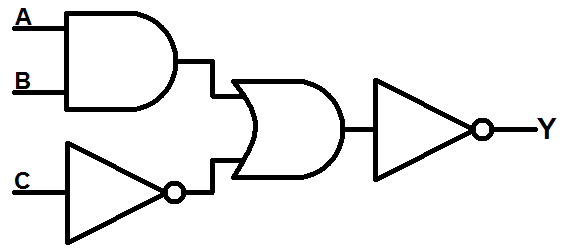
Factorio combinators setup are actually much closer to circuit logic boards designs then programming and in the circuit logic board designing world, circuits diagrams are the norm and very common. Not flow charts mind you. Something like this.

Image
Image
Image

Gus_Smedstad
Fast Inserter
Fast Inserter
Posts: 163
Joined: Fri May 16, 2014 2:30 pm
Contact:

Re: Talking about the circuit design process

Post by Gus_Smedstad »

As a kid I used to mess with basic logic diagrams like that - because programming wasn't yet an option. I didn't understand analog circuits at the time, but I could handle all the basic logic gates, and of course a lot of more complex standard circuits like D flip-flops.

That said, diagrams are not easy design tools. There's a reason why CPUs went from hardwired gate-based decoders to microcode decades ago. It's just a lot easier to deal with the abstractions with pseudo-code and formal logic, resorting to actual gates only when you're clear on your approach. Circuits are in effect the "machine language" of these logic problems; they're how the results are implemented, but they're the hardest representation of a solution to understand and change.

User avatar
ssilk
Global Moderator
Global Moderator
Posts: 12888
Joined: Tue Apr 16, 2013 10:35 pm
Contact:

Re: Talking about the circuit design process

Post by ssilk »

See this suggestion:
https://forums.factorio.com/forum/vie ... =6&t=14212 Compound Combinators (complex logic in a single building)

Building up logic in that way makes sense in my eyes. :)
Cool suggestion: Eatable MOUSE-pointers.
Have you used the Advanced Search today?
Need help, question? FAQ - Wiki - Forum help
I still like small signatures...

Zhab
Fast Inserter
Fast Inserter
Posts: 101
Joined: Sat Jul 18, 2015 10:17 pm
Contact:

Re: Talking about the circuit design process

Post by Zhab »

Gus_Smedstad wrote:As a kid I used to mess with basic logic diagrams like that - because programming wasn't yet an option. I didn't understand analog circuits at the time, but I could handle all the basic logic gates, and of course a lot of more complex standard circuits like D flip-flops.

That said, diagrams are not easy design tools. There's a reason why CPUs went from hardwired gate-based decoders to microcode decades ago. It's just a lot easier to deal with the abstractions with pseudo-code and formal logic, resorting to actual gates only when you're clear on your approach. Circuits are in effect the "machine language" of these logic problems; they're how the results are implemented, but they're the hardest representation of a solution to understand and change.
Well I was only suggesting to use diagrams to share a finished circuit. For that purpose, I strongly disagree that a circuit diagrams are inherently harder to understand than pseudo-code. The reason being that pseudo-code will be significantly different than the actual resulting circuits. This is already the case with very simplistic projects, I don't even want to know how much the pseudo-code for a circuit involving 50+ combinators (that isn't 1 circuit repeated over) would be different from the actual circuit.

When actually building the final product, a diagram would be drastically easier to understand and to follow. If later on you build around your factory and need to relocate the input of a specific signal or you need to move a few combinator around, a diagram will be immensely more useful than pseudo-code to tell you where you can relocate cables and stuff in such a way that will preserve the integrity and function of the circuit. Sharing a circuit with a diagram allow people to easily build and use it without having to worry about how the pseudo-code actually translate into a physical factorio build.

For example, you seem like a smart person to me who knows his way around computers. You do not seem to have any problem coming up with a sound logic for a circuit. But when it comes to actually building it you have a tendency to over engineer things or struggle with how to handle specific circuit tasks. Now if a smart person like you have this problem, I would imagine that other people who are less comfortable with combinator logic and perhaps have dodgy engineering skills at best would have even more trouble transforming pseudo-code into a functional factorio circuit. As such, a diagram would definitively be more useful to them than an easy to understand pseudo-code that they can't actually use in game because their understanding of combinators vs text code just isn't that good.

The only times pseudo-code is actually useful to have is for the initial logic structure design phase and for when you want to modify the overall behavior of the circuit. Now I understand that this thread is about circuit design and not circuit sharing. So now that I've clarified my reasoning behind why diagrams have their place, I wont talk about this again (unless you choose to continue this discussion).

Post Reply

Return to “General discussion”