Simple hysteresis with two combinators

This board is to show, discuss and archive useful combinator- and logic-creations.
Smart triggering, counters and sensors, useful circuitry, switching as an art :), computers.
Please provide if possible always a blueprint of your creation.
Post Reply
Z903
Burner Inserter
Burner Inserter
Posts: 16
Joined: Wed Oct 22, 2014 7:18 am
Contact:

Simple hysteresis with two combinators

Post by Z903 »

You can use a two combinator solution to implement hysteresis in any system.
Image

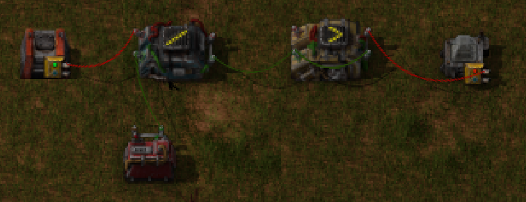
So quick explanation.
C = negative of the center value
H = hysteresis, plus minus this are your trigger points

Constant: C
Arithmetic: each / H
Decider: each > 0 = 1 each
So if you wanted 40, 60 you set C = -50, H = 10

The system works because the divider rounds towards zero. We adjust the input to be centered around zero with the constant. So -9 to 9 outputs 0, but -10/10 outputs -1/1. These trigger the decider that stores the current state.

Simple!

golfmiketango
Filter Inserter
Filter Inserter
Posts: 549
Joined: Fri Jan 29, 2016 2:48 am
Contact:

Re: Simple hysteresis with two combinators

Post by golfmiketango »

Pretty sweet idea, thanks for sharing!

suprnova74
Long Handed Inserter
Posts: 61
Joined: Thu Sep 10, 2015 2:29 am
Contact:

Re: Simple hysteresis with two combinators

Post by suprnova74 »

hysteresis.png
hysteresis.png (695.82 KiB) Viewed 30443 times
It took me a while to figure out the various bits, but "C" should be the content type you're monitoring. in this example, it's crude oil set to -500 with a (H)ysteresis of 50 points (set for the example for quick triggering). Hope this helps others if they need a similar setup. this is useful to barrel heavy/light oil during early production when you primarily need hydrocarbons while not emptying everything

User avatar
impetus maximus
Smart Inserter
Smart Inserter
Posts: 1299
Joined: Sat Aug 20, 2016 10:07 pm
Contact:

Re: Simple hysteresis with two combinators

Post by impetus maximus »

how does this differ from a SR latch circuit?

suprnova74
Long Handed Inserter
Posts: 61
Joined: Thu Sep 10, 2015 2:29 am
Contact:

Re: Simple hysteresis with two combinators

Post by suprnova74 »

might be, I really haven't delved into logic networks much and this was the first post I hit when I had a need.

golfmiketango
Filter Inserter
Filter Inserter
Posts: 549
Joined: Fri Jan 29, 2016 2:48 am
Contact:

Re: Simple hysteresis with two combinators

Post by golfmiketango »

impetus maximus wrote:how does this differ from a SR latch circuit?
An SR latch does something completely different. Hysteresis, as used here, means that a certain range of values are "accepted" by the circuit and everything else is "rejected". This device accepts a single continuous stream of values as an input and returns a corresponding continuous stream of one's and zero's that "accept" or "reject" the input.

For example, a power supply is a kind of hysteresis circuit. It accepts a range of power inputs from zero up to the maximum amount of power it is rated for; beyond that, the fuse will blow. Almost everything in real-life is this way: there's a limit to how positive or negative you can go before you run out of something or blow something up.

Hysteresis is a practical tool in circumstances where one wants to do something useful while avoiding various disasters like explosion, electrocution, bankruptcy, etc., and is to be found in digital and analog devices of all kinds.

An S/R latch is more of an intrinsically digital concept where one toggles or takes a snapshot of something when a button gets pressed.

User avatar
impetus maximus
Smart Inserter
Smart Inserter
Posts: 1299
Joined: Sat Aug 20, 2016 10:07 pm
Contact:

Re: Simple hysteresis with two combinators

Post by impetus maximus »

cool. thanks for the explanation golfmiketango. :)

Z903
Burner Inserter
Burner Inserter
Posts: 16
Joined: Wed Oct 22, 2014 7:18 am
Contact:

Re: Simple hysteresis with two combinators

Post by Z903 »

I think of it more as upper and lower trigger points. If a value rises above the upper trigger turn on, if it fall below the lower trigger turn off. If the value is between the upper and lower triggers keep the current state.

golfmiketango
Filter Inserter
Filter Inserter
Posts: 549
Joined: Fri Jan 29, 2016 2:48 am
Contact:

Re: Simple hysteresis with two combinators

Post by golfmiketango »

golfmiketango wrote:
impetus maximus wrote:how does this differ from a SR latch circuit?
An SR latch does something completely different. Hysteresis, as used here, means that a certain range of values are "accepted" by the circuit and everything else is "rejected". This device accepts a single continuous stream of values as an input and returns a corresponding continuous stream of one's and zero's that "accept" or "reject" the input.

For example, a power supply is a kind of hysteresis circuit. It accepts a range of power inputs from zero up to the maximum amount of power it is rated for; beyond that, the fuse will blow. Almost everything in real-life is this way: there's a limit to how positive or negative you can go before you run out of something or blow something up.

Hysteresis is a practical tool in circumstances where one wants to do something useful while avoiding various disasters like explosion, electrocution, bankruptcy, etc., and is to be found in digital and analog devices of all kinds.

An S/R latch is more of an intrinsically digital concept where one toggles or takes a snapshot of something when a button gets pressed.
The above -- I mean, my response to impetus maximus -- is just basically wrong. It's some kind of brain fart -- I suspect I was working on too many combinator posts at once.

It's too late, now, to just fix my original answer, since the conversation has already moved on, so I'll correct myself here.

The thing that bugs me most about my post above is that I rudely managed to sound as if impetus maximus is totally confused, whereas I know exactly what's up; precisely the opposite appears to have been the case! Oh well, sorry about that.

To atone, let's try to answer your question properly impetus: first, let's clear the whiteboard of garbage:
  • Hysteresis is different from an S/R latch but not "completely" different -- what would that even mean? Indeed it's got a bunch of similarities.
  • The thing about hysteresis being analog <-> digital while an SR latch is <digital> <-> <digital> is quite correct. As is the stuff about practical applications ("electrocution" and "bankruptcy"). To bad I put all that other garbage in there, as this could have been the beginnings of a useful answer :)
  • The rest of my post above should be ignored. Even the correct parts are poorly stated.
Let's try again to answer the question properly:

What is an SR latch? The standard factorio SR latch is, I think, the one from the "combinators 101" post with two A=0 --> A:1 deciders.

It has somewhat complicated dynamics when you start to look at corner cases, but the basic idea is it has a "set" input and a "reset" input. When it's off, providing a brief (but not too brief) "1" pulse to it's "set" pin will turn it on (cause a 1 to be output), and once it's on, providing a brief (as before) "1" input to is "reset" pin will turn it back off (cause a zero to be output). It is often talked about as a "switch" but that's pretty cavalier. Generally speaking, an S/R latch is in fact not a true switch -- we have a true switch in the game, now, and it's easy to see that what it does is quite different from what an S/R latch does. But the idea and i/o interface of a switch is so familiar that it's hard not to think of it that way. Calling it a switch is more like a metaphor than a technical description. An accurate but confusing way to describe an S/R latch is that it's a one-bit digital storage device, which continuously outputs its stored value, and is controlled by a two-bit (no pun intended) pulse-controlled digital interface which sets or unsets the stored bit depending on whether the "set" or "reset" input bit is pulsed, respectively.

What is hysteresis? Some of that has been covered above. Note that the term is quite broadly defined and used. Any device that goes "pop! or "ker-chunk" probably makes that noise due to some kind of hysteresis. To avoid vague generalizations, however, let's limit our discussion to the Z903 device in the OP.

The Z903 device inputs a "program" from a constant combinator. The program should not change (changing it at the wrong moments will probably break it). It also inputs a single red or green wire and operates on its value. It has the same output interface as the S/R latch: a single bit of information per tick. Like the S/R latch, it acts as a one-bit storage device; but in the S/R latch, the bit is togglable arbitrarily whereas the Z903 device toggles itself based on the input and the "program" from the constant combinator.

The constant-combinator input to the Z903 device effectively creates a contiguous range of values with an upper and a lower limit. The particular way to tell it this range is to take the average of the minimum and the maximum, and multiply by -1, and put this in the signal slot corresponding to the resource being ranged (i.e., iron plates). This is what z903 calls the "center value". It also inputs an "H" there which is 1/2 the width of the range. So, if you want to say iron plates from 30 minimum to 50 maximum you would put Iron=-40, H=10 into the constant combinator.

Put another way the minimum of the range will be (-plates - H) and the maximum will be (-plates + H) ... I'm probably ignoring a bunch of off-by-one mistakes here but that's the gist of it.

Armed with this knowledge it's quite simple to finish the black-box explanation: The device will turn on it's memory-bit once you go below the minimum and turn it off again, above the maximum -- that's it.

What's it good for? All kinds of stuff.

Often in factorio we want some kind of Relaxation Oscillator. The classic example is to turn your boilers on when your accumulators get low. The fundamental problem we are trying to solve there is that we can't just say "Turn on the boilers when the accumulators drop below "40%": Why not? If we do that, what will happen is, the boilers will activate at 39% charge, charge the accumulators up to 40% and then deactivate, and, since, of course the accumulators were discharging in the first place, they will go immediately back to 39%, the boilers will turn back on until they reach 40% and so on, back and forth between 39 and 40 until the biters come home.

In that system, the accumulators never leave the "danger zone" by much, and the boilers never get up to full speed. At best it achieves some kind of weird stuttery pseudo-activation but it's basically not the behavior anyone would want in normal game play. Although it may be just enough functionality to avert total disaster, it clearly did what you "said" instead of what you "meant" when you tried to program your boilers to activate on low power.

OK, Steam Backup Mark II: If power below 40% any time in the past 10 minutes, activate boilers. This is much better but quite sloppy. We end up charging the accumulators completely and continue running the boilers for no good reason if the factory is idle. But if the factory is drawing lots of power -- enough to soak up most of the electricity the boilers provide, let's say, at dusk -- the accumulators might still never charge up past 40% -- in this case, we may have slowed down the stutter frequency, but failed to fix the stuttering problem of the Mark I.

Steam Backup Mark III, the solution most people go with, is to implement hysteresis. When power goes below 20%, activate the boilers, and then keep them on, until the accumulators reach 60%. This approach is so natural that most of us are surprised when that's not what happens in the Mark I. If we asked a human to turn on the boilers when the power is below 40% the wouldn't turn them off the moment 40% power was restored, but combinators are not AI's, and they don't give a shit about your problems. The contraption in the OP does precisely this.

It can be very confusing to get hysteresis right once you figure out that you need it. The system can no longer just look at the accumulator and decide if the boilers should be running. When charge is between 21% and 59%, we want to just keep the boilers running, or not running, as they were. But the system cannot "do nothing", because that would turn the boilers off even if they were on -- so we need some kind of memory. The obvious solution is to make an S/R latch and two deciders to implement this, which works fine.

But z903's implementation is more elegant, and, by having less combinators, consumes 50% less of the power it regulates in this example. There are, perhaps, better solutions involving activating more or less boilers depending on how low the charge is; but that's another topic, and anyhow, they still need hysteresis.

EDIT: In my boiler example, the hysteretic conditions are "reversed" from how they are normally arranged (bigger on, smaller off). To make the right thing happen, we can simply set H=-20, A=-40 instead of H=20, A=-40.

Z903
Burner Inserter
Burner Inserter
Posts: 16
Joined: Wed Oct 22, 2014 7:18 am
Contact:

Re: Simple hysteresis with two combinators

Post by Z903 »

A reddit thread by Vox_Imperatoris was posted earlier today. They put together a similar solution using a diffrent method.
https://www.reddit.com/r/factorio/comme ... ry_simple/

Its awesome to see how many ways things can be created in factorio. The only issue I see with their solution is it would be unstable with a 1 tick pulse.

User avatar
siggboy
Filter Inserter
Filter Inserter
Posts: 988
Joined: Tue Mar 29, 2016 11:47 am
Contact:

Re: Simple hysteresis with two combinators

Post by siggboy »

Here's a different design towards the same end: viewtopic.php?f=6&t=28899&start=50#p189046

This design is very similar to a Schmitt Trigger you would build with an Op-Amp and some resistors, in an actual digital circuit.

XKnight has also posted a solution in that thread which is even one tile smaller (1 decider + 1 constant), but more difficult to understand.
It can be very confusing to get hysteresis right once you figure out that you need it. The system can no longer just look at the accumulator and decide if the boilers should be running. When charge is between 21% and 59%, we want to just keep the boilers running, or not running, as they were. But the system cannot "do nothing", because that would turn the boilers off even if they were on -- so we need some kind of memory. The obvious solution is to make an S/R latch and two deciders to implement this, which works fine.
Latch + 2 deciders is the most straightforward approach, but the functionality is not different in the solutions linked above, which only require 2 combinators. XKnight's solution exploits a quirk in the decider combinator, that only works if you use the "each" virtual signal. It's a bug in my opinion.
Is your railroad worrying you? Doctor T-Junction recommends: Smart, dynamic train deliveries with combinator Magick

Z903
Burner Inserter
Burner Inserter
Posts: 16
Joined: Wed Oct 22, 2014 7:18 am
Contact:

Re: Simple hysteresis with two combinators

Post by Z903 »

You have an interesting design siggboy, looks like Vox_Imperatoris built the same one as you. XKnight has a really cool design, took me a while to figure it out.

Splitframe
Long Handed Inserter
Posts: 54
Joined: Thu Aug 28, 2014 4:44 pm
Contact:

Re: Simple hysteresis with two combinators

Post by Splitframe »

Not to necro this old thread, but it's the first entry when you google "factorio hysteresis blueprint".
So if you happen to land here from google here is a simple version withouth tens of combinatiors:
https://www.factorio.school/view/-MGa-sAK2Wtkks1efX1c

Post Reply

Return to “Combinator Creations”