Circuit Network help

Don't know how to use a machine? Looking for efficient setups? Stuck in a mission?
stergil
Burner Inserter
Burner Inserter
Posts: 8
Joined: Tue May 14, 2019 3:23 pm
Contact:

Circuit Network help

Post by stergil »

I've started to dabble with the circuit network and combinators and am having trouble wrapping my head around a few things. After much searching online I found some examples to help get me to a starting point but I'm having trouble putting things together.

I have a series of Arithmetic and Decider combinators on a segment of track heading into a holding yard for trains available to be dispatched. This counter (A) works perfectly fine in that it continues to increment as trains pass the track segment.

There's another segment of track past the dispatch station which counts the trains as they leave (D).

Incrementing each counter as trains pass works great. However, I need to decement the Dispatch (D) counter based on the Available counter (A) and vice versa. When a train returns to being Available, D needs to decrement one. When a train is dispatched, A needs to decrement one.

I've played with this quite a bit and feel like I've hit a wall so I was hoping I could get some help. I realize the LTN mod does this better than I ever could, but my goal is to understand what's going on and use vanilla - not simply get the end result.

In addition to this problem, I was hoping to get operational clarification on the counter I'm using. I don't recall what forum/reddit/google search I found it in.

Questions:
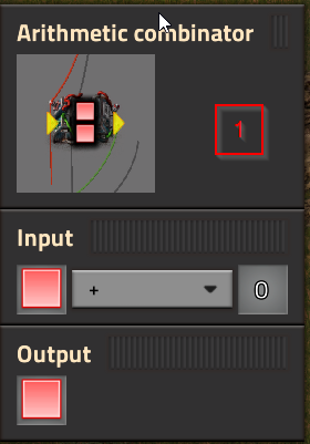
  • Why is Combinator #1 necessary? If I exclude it, the counter jumps by values of 20 - why?
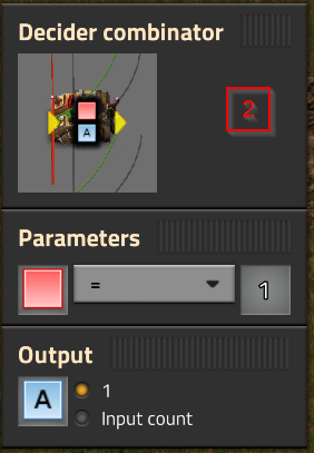
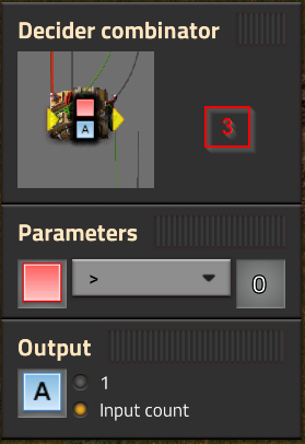
  • Why is the Red output from Combinator #1 insufficient for the subsequent Decider combinators? If I remove the red wire from #2 and #3 it fails to work. I'd have expected the Red signal coming from #1 to satisfy the Red = or > 1 evaluation.
  • How is Combinator #3 preventing a double-add in value? If I remove it from the chain the counter increments twice - once as the train enters and and once as it exits the signal block
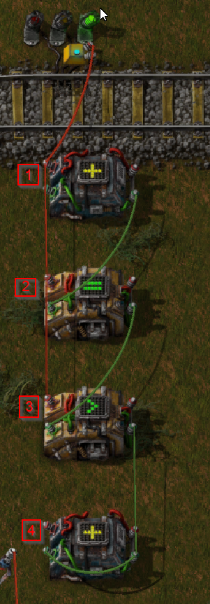
Image
ImageImageImageImage
stergil
Burner Inserter
Burner Inserter
Posts: 8
Joined: Tue May 14, 2019 3:23 pm
Contact:

Re: Circuit Network help

Post by stergil »

This excellent write-up viewtopic.php?f=193&t=14556 and detailing my problem in the forum post got me thinking more clearly. I think I have it working as desired now although my questions about the counter remain.

The counters working allows me to do what I want, but I'm not 100% clear on how the counter works.
The Eriksonn
Fast Inserter
Fast Inserter
Posts: 230
Joined: Wed Jun 08, 2016 6:16 pm
Contact:

Re: Circuit Network help

Post by The Eriksonn »

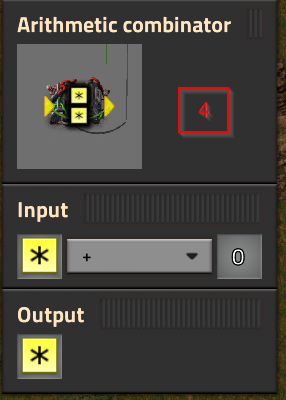
Combinators 1-3 are for turning the long red signal into a 1 tick pulse so that combinator 4 adds one every time the signal registers a train.
In other words: It should output a signal for precisely 1 tick when the input changes from 0 to 1.

here it is very important to remember that a combinator outputs its value one tick after it has receved it.
in the following steps i show the output as it will be outputted in the next tick, ie their inputs are the outputs of the previous tick
I find it easier to think about these timing bases systems by doing a tick by tick step through of the whole system like this:
this is for when it "turns on", ie the input goes from 0 to 1
Tick 1:
C1: red:1 => red:1
C2: red:1 => A:1 -- this one has not yet recieved the 1 red from C1 so it outputs A
C3: red1,A:0 => A:0
C4: A:0 => A:0

Tick 2:
C1: red:1 => red:1
C2: red:2 => A:0 -- now when it has recieved it it doesnt output A anymore, this is what is causing the 1 tick pulse for C4 to increase
C3: red:1, A:1 => A:1 -- just passing through the A as red is on
C4: A:0 => A:0

Tick 3:
C1: red:1 => red:1
C2: red:2 => A:0
C3: red:1, A:0 => A:0
C4: A:1 => A:1 -- sucessful increment

Tick 4+: no change

and this is for turning off
Tick 1:
C1: red:0 => red:0
C2: red:1 => A:1 -- it fired again when the signal turned off, if it wasnt for C3 this would cauce C4 to increment here too, but we dont want that.
C3: red0,A:0 => A:0
C4: A:1 => A:1

Tick 2:
C1: red:0 => red:0
C2: red:0 => A:0
C3: red0,A:1 => A:0 -- this one is only here to prevent the pulse from reaching C4 when the signal changes in the other direction, as it turns off before A can reach it
C4: A:1 => A:1

Tick 3+: no change

I hope this has cleard up what role each of the different combinators have, and Why all parts are needed to make a working counter
Post Reply

Return to “Gameplay Help”