
I decided to build this for two reasons:
- I wanted to learn combinators. When I started this I had never used a single combinator and had no idea how they worked or what they could be used for.
- I wanted to build something that would allow a list of names (or something else) to be displayed and rather easily manipulated – especially for those who have no prior experience with combinators.
Here is a short YouTube video that will give you an idea of what the actual build is and its purpose.
Before I go any further I would like to take the time to thank two people in particular; HanziQ who built the binary decoder that is the heart of this build (more info on that later), gave me a crash course in binary and gave ideas for making the build possible; and Melerion who also helped teach me binary and assisted with some ideas and troubleshooting I had for the build. Massive thank you to the both of you!
I am going to go into further detail about how the actual build works and each small component to it. Part of this will assume that you have a basic knowledge of decimal binary, if you don’t I found this video after a quick search on YouTube – it’ll give you a basic understanding (note only the first 1:45 of the video is relevant to what we need). Note that I will not be going into extreme levels of detail on what the combinator settings are and the wiring; to do so would be simply too complex. Instead, I will give you an idea of what each component in the build does and how they work together as a whole.
Ok, so breaking the build down and looking into each component:
The Displays & Memory Cell
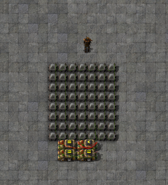
Each display is made up of lights in a grid of size 7 long X 8 high. The lights on the outer layer have no condition set as they will never be turned on, however they are still wired together as to avoid them turning on at night. The lights in the centre comprises of a grid that is 5 long X 6 high and these lights are what we use to actually display letters. Each of these lights is set with a condition of “[Item] = 1” and each light has a different item signal assigned to it; this allows us to create an image (in this example we are creating letters, but you can make custom letters, symbols, etc). When we send a signal to the light grid the corresponding lights will turn on and that’s the visual output that we see.
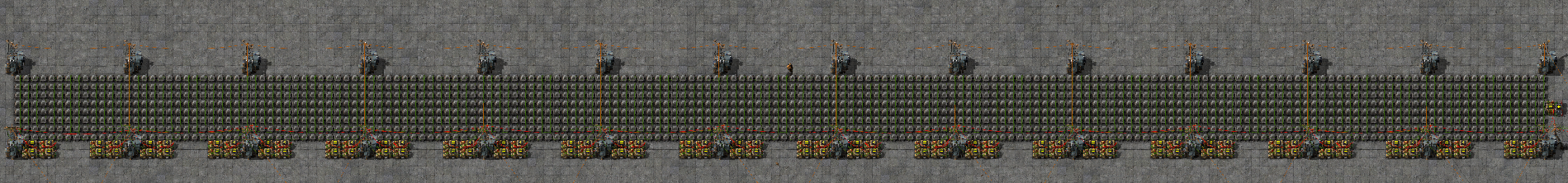
These displays are put together 26 long in order to see a complete panel as shown:
The memory cell allows us to retain and ‘save’ a bunch of signals that are sent from the binary decoder. This means that after we finish sending the correct signals to make a letter the cell will hold these signals and our visual output will remain in place. These cells have two important signals that can be sent to them in order to control what they are doing; a Red signal of value 1 is the write signal – meaning anything that any signal inserted to the memory cell (when accompanied by a Red = 1 signal) will get ‘saved’, a Red signal of -1 is the clear signal – it will release any signals currently being held in the cell and give us a clean cell to be used.
Just before the memory cell is what I call an identifier combinator – this combinator dictates what number along the line the grid is. (In this build each line is 26 grids long – ie. You can show 26 letters per line).
By combining the display grid and the memory cell we have all we need to save and display letters. Putting these side-by-side we can see the creation of a line on the display which we can add names or whatever it is that you wish to output.
The Alphabet
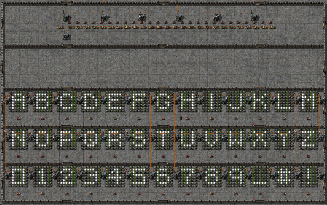
So this is where we need an understanding of decimal binary to see what’s going on. I have created a small display to show each letter of the alphabet, numbers 0-9 and a few common symbols. Below each of these displays there is a corresponding constant combinator that will contain a signal of “0 = [number]”. This signal is what we will feed into the binary decoder in order to ‘create’ an image from this number. We use this alphabet as a means of creating new names which we can then put on a list which will be read by the binary decoder.
A Name
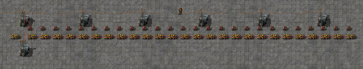
This is what a built name will look like ready to input through the binary decoder. There is a blank template of this within the alphabet area that we can use to easily make a new name. These names are then placed on top of each other in order to create a list. Note that the very left decider combinator for each name will have properties of "Green Signal = <constant>"; this constant dictates the order in which the name will appear on the list (ie. if you want that name to show first make the condition "Green signal = 1", for two it would be "Green signal = 2" etc). The best way of thinking about this part of the build is that it is the ‘hard drive’ which stores all the data that we will run through the decoder.
The ‘Brain’
This module is what I refer to as the ‘brain’ of the build. It is responsible for processing and controlling a number of things, including;
1. Referencing the names list (data)
2. Decoding the incoming binary signal
3. Sending signals to the corresponding grids
4. Automatically adjusting for total number of panels
5. Activating and clearing the sign
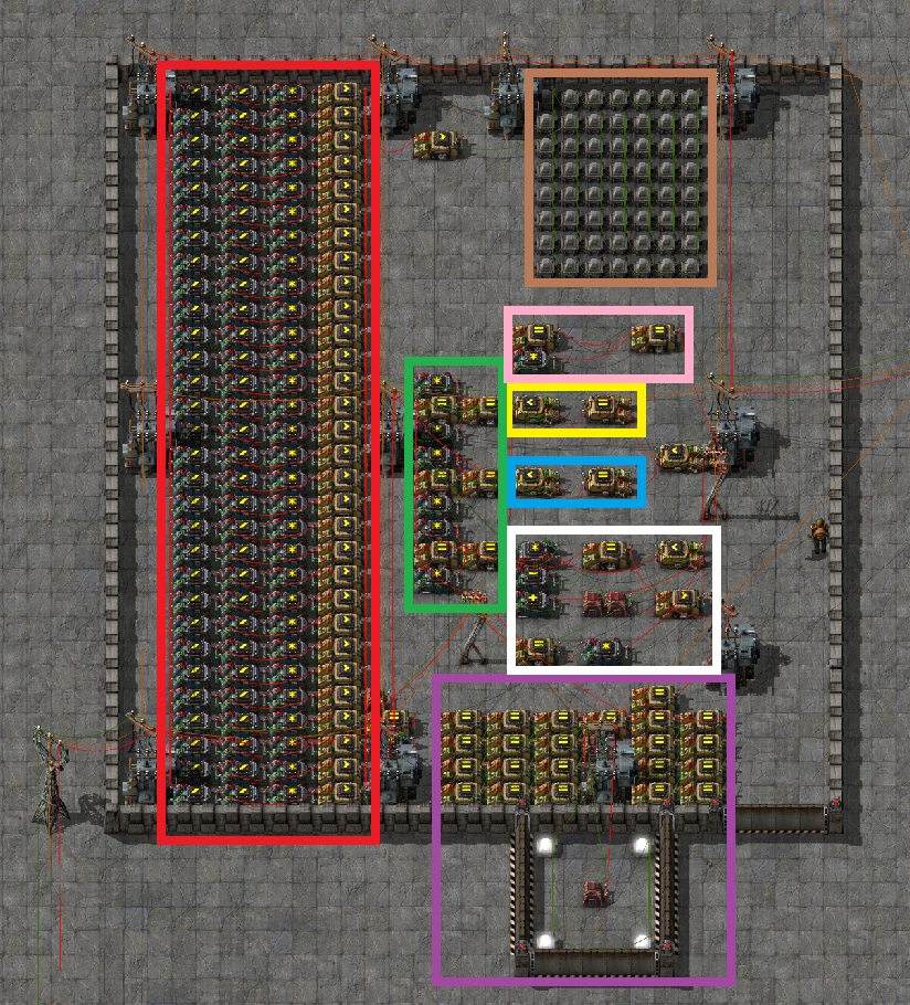
Since this bit is quite advanced I’ll break it down a bit. Refer to the above picture to see each part.
Red - This is the binary decoder; it takes the input signals coming from the names list (in the form of decimal binary) and decodes these into signals that we use to light up each display.
Brown - This light display is simply here so the output of the binary decoder can be seen as it runs through reading the names list.
Green - These combinators are used as part of the reset mechanism. They are pulse generators that read whatever the values of the counters are and when activated send a signal for a negative value of whatever is in the counters for one tick, thus clearing the signal.
Pink - This mechanism tells the system when a panel has been completed and adds a green signal +1 value meaning that the system will start on the next panel.
Yellow - The counter to cycle through and reference the names list.
Blue - The counter to cycle through and write the output of the decoder to the corresponding grid.
* Note that these two counters (the yellow and blue sections) are setup to work 7 ticks apart - meaning that each letter takes 7 ticks to be referenced, put through the decoder and then written to it's grid.
White - This counts and tells the system which panel it is currently reading/writing to. It also contains a mechanism to stop and 'jam' the counters when the whole process has completed to avoid the system running continuously even when finished.
Purple - This is the activation system. In order to give the system time to reset properly the read and write system is delayed by two pulse generators. The reset system is on the left and write system on the right.
The whole system is activated and reset simply by changing the value of the green signal in the constant combinator just below the brain (value of 0 to reset, value of 1 to activate).
For a tutorial on adding new names to the display please follow this guide.
The save file provided will have the whole build wired together correctly, however if you wish to put this build into your own world you can follow the wiring guide here.
If you have any questions regarding this build feel free to leave a comment and I'll do my best to answer.
Enjoy!


