Combinator Contraptions
-
Sander Buruma
- Fast Inserter

- Posts: 100
- Joined: Mon Jun 02, 2014 9:55 am
- Contact:
Re: Combinator Contraptions
I'd really like for lights to be able to change color according to the value of a signal.
-
Lupoviridae
- Fast Inserter
- Posts: 155
- Joined: Mon Apr 20, 2015 6:26 pm
- Contact:
Re: Combinator Contraptions
This can be done with some smart chests, though its a little bulky. You can measure how many pass through the chests in a certain amount of time.Peter34 wrote:I'd love to see a Sensor to measure Belt throughput, but I don't know that the devs have any such plans.ratchetfreak wrote:or the amount of ore going through a belt.
-
Lupoviridae
- Fast Inserter
- Posts: 155
- Joined: Mon Apr 20, 2015 6:26 pm
- Contact:
Re: Combinator Contraptions
This is in the roadmap for 0.13 last I heard.Sander Buruma wrote:I'd really like for lights to be able to change color according to the value of a signal.
Re: Combinator Contraptions
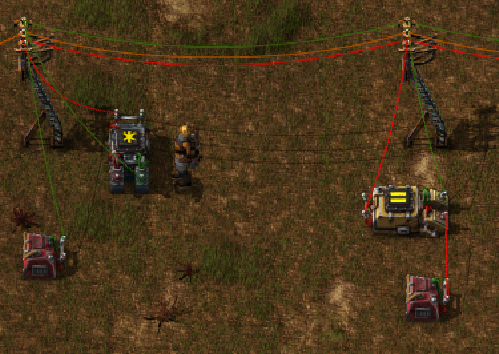
Came up with a basic register that works without having to break numbers down into binary first, just stores a 32-bit input value directly in a combinator when it gets a write signal.

red wire on the right pole is for inputs; two inputs are expected, the value to write, which is currently expected as some number of crude oil barrels, and the write signal, which is on signal '1'. the write will occur the cycle after this changes to 1. It is not a continuous write - changing the input count while holding the write signal at 1 will NOT keep the register updated, the write happens once the moment the write signal goes to 1! For it to work properly as in the blueprint, it is important that the input wire network NOT have any '0' signal on it, as it is used internally and an outside value will break the register.
Output is also in crude oil barrels and is carried on the green wire on the left pole. It's using oil barrels because of the test setup I was using it on, but can be changed to any other item type or signal easily, just open the guis on the four arithmetic combinators and change the types of their input and output from crude oil barrels to whatever you want.
I wanted this to be easily usable as-is, but note that the top-right decider combinator is not, strictly, part of the register; it simply converts the input signal into a normalized signal for the rest of the circuit. You can freely modify that combinator's settings to your situation; whatever condition makes it output 1 will trigger the write when it happens.
if you're trying to work out the wiring to reverse-engineer it, a tip: reversing combinators (hover and 'r') doesn't affect wiring, so it makes it possible to see wires that are too small (as between adjacent combinators) or ambiguous in which they're connected to.
The test rig above the register has a smart chest, containing some number of oil barrels as the input; the constant combinator outputs the signal on '1' that triggers a write.
The green output wire is connected to the smart chest and two inserters on that side. The inserters use a condition "solid fuel < oil barrels" and "solid fuel < oil barrels" and will insert or remove solid fuel so that the amount in the left chest equals the value of the register. This example is not terribly useful - almost the same could be accomplished by just connecting the right chest into the circuit, without any combinators - but it has the benefit of being clocked by the write signal, so the inserters won't just be constantly fiddling with items if the right chest is being used in some system.
As a more practical example, I'm using this system currently on carriages for oil. Here's a screenshot of the test station from when I was developing the system:

(it looks different, as I was still prototyping the register and so didn't have the blueprint yet, but the register is exactly the same)
When a train arrives (as detected using a method based on /u/freetambo's post about combinators and trains on reddit) the smart smart inserter that unloads empties from the station chest back to the factory is disabled (it will be empty at this point unless the station is completely overstuffed) and a register like this one gets a write signal, saving the amount of filled oil barrels in another chest awaiting loading. I pass that value through a pair of arithmetic combinators, which divide by 10, which gives the number of stacks of these full barrels, then multiplies back by 10 to give the number of barrels in stacks. The smart inserter removing from the train is connected to the register's output and it's own chest, and pulls on the condition "empty barrel < crude oil barrel," so it pulls exactly as stacks of empties as there are stacks of full to replace. Loading the full barrels just uses a smart inserter with no conditions.
The result is that each oil outpost using this setup loads only full stacks of oil barrels, and unloads exactly as many empty barrels as necessary to replace the ones going out, so all my outposts maintain a constant number of total barrels, without having to saturate every outpost with barrels or deal with most of the issues that can normally come with managing the supplies of empties and have, in the past, led me to stop trying to keep full and empty barrels in the same carriage.
This is just one possible application, I have no doubt I will come up with others over time; how practical and justified it is as a solution to a relatively minor problem is entirely subjective, of course, but I'm extremely pleased with the results.
blueprint
I included the power poles in the blueprint to make it easier to connect things without having to know and remember which of the 8 combinators do what.red wire on the right pole is for inputs; two inputs are expected, the value to write, which is currently expected as some number of crude oil barrels, and the write signal, which is on signal '1'. the write will occur the cycle after this changes to 1. It is not a continuous write - changing the input count while holding the write signal at 1 will NOT keep the register updated, the write happens once the moment the write signal goes to 1! For it to work properly as in the blueprint, it is important that the input wire network NOT have any '0' signal on it, as it is used internally and an outside value will break the register.
Output is also in crude oil barrels and is carried on the green wire on the left pole. It's using oil barrels because of the test setup I was using it on, but can be changed to any other item type or signal easily, just open the guis on the four arithmetic combinators and change the types of their input and output from crude oil barrels to whatever you want.
I wanted this to be easily usable as-is, but note that the top-right decider combinator is not, strictly, part of the register; it simply converts the input signal into a normalized signal for the rest of the circuit. You can freely modify that combinator's settings to your situation; whatever condition makes it output 1 will trigger the write when it happens.
if you're trying to work out the wiring to reverse-engineer it, a tip: reversing combinators (hover and 'r') doesn't affect wiring, so it makes it possible to see wires that are too small (as between adjacent combinators) or ambiguous in which they're connected to.
The test rig above the register has a smart chest, containing some number of oil barrels as the input; the constant combinator outputs the signal on '1' that triggers a write.
The green output wire is connected to the smart chest and two inserters on that side. The inserters use a condition "solid fuel < oil barrels" and "solid fuel < oil barrels" and will insert or remove solid fuel so that the amount in the left chest equals the value of the register. This example is not terribly useful - almost the same could be accomplished by just connecting the right chest into the circuit, without any combinators - but it has the benefit of being clocked by the write signal, so the inserters won't just be constantly fiddling with items if the right chest is being used in some system.
As a more practical example, I'm using this system currently on carriages for oil. Here's a screenshot of the test station from when I was developing the system:
(it looks different, as I was still prototyping the register and so didn't have the blueprint yet, but the register is exactly the same)
When a train arrives (as detected using a method based on /u/freetambo's post about combinators and trains on reddit) the smart smart inserter that unloads empties from the station chest back to the factory is disabled (it will be empty at this point unless the station is completely overstuffed) and a register like this one gets a write signal, saving the amount of filled oil barrels in another chest awaiting loading. I pass that value through a pair of arithmetic combinators, which divide by 10, which gives the number of stacks of these full barrels, then multiplies back by 10 to give the number of barrels in stacks. The smart inserter removing from the train is connected to the register's output and it's own chest, and pulls on the condition "empty barrel < crude oil barrel," so it pulls exactly as stacks of empties as there are stacks of full to replace. Loading the full barrels just uses a smart inserter with no conditions.
The result is that each oil outpost using this setup loads only full stacks of oil barrels, and unloads exactly as many empty barrels as necessary to replace the ones going out, so all my outposts maintain a constant number of total barrels, without having to saturate every outpost with barrels or deal with most of the issues that can normally come with managing the supplies of empties and have, in the past, led me to stop trying to keep full and empty barrels in the same carriage.
This is just one possible application, I have no doubt I will come up with others over time; how practical and justified it is as a solution to a relatively minor problem is entirely subjective, of course, but I'm extremely pleased with the results.
My Mods:
Nixie Tubes - numeric displays for your circuit networks!
Logistic Combinators - use logistics values in circuit logic! -
Autowire - automate red/green wire connections
Nixie Tubes - numeric displays for your circuit networks!
Logistic Combinators - use logistics values in circuit logic! -
Autowire - automate red/green wire connections
-
Lupoviridae
- Fast Inserter
- Posts: 155
- Joined: Mon Apr 20, 2015 6:26 pm
- Contact:
Re: Combinator Contraptions
I came up with my own register, capable of storing any value for any given items. For example, it could store 512 iron plates, 210 copper, and 123 coal, all in one register. It essentially takes a snapshot of everything currently on the red circuit.
A couple things to keep in mind:
iE means output Everything (input count)
In implementation, the wires labled red and green would all be connected to a main bus. I ommitted this in the diagram to make it easier to read.
Input for each box is on the left, output is on the right.
Here's the wiring diagram:
Combinator 6 in the diagram is what does the heavy lifting, and it works by using "pulsed" (single tick length) signals. For this reason I call it a "Pulsed-Value Register" or "PVR".
In this setup, the green wire carries the read ("0") and write ("1") signals as well as the address ("A"), while the red wire carries data.
The first pulse of a green signal to that combinator causes it to remember all current input values. The next clears the memory. This does mean that before it can be used, the register must fist be initialized with a single green pulse, which can be done by disconnecting one of the combinators labeled 4 and performing a dummy write.
Here's the breakdown of what each component does:
1) If the address signal ("A" == 5) and write ("1" == 1) are both enabled, outputs "Blue" == 2
2) If "Blue" == 2, outputs "Red" == 1. This gets added to the constant combinator for a total signal of "Red" == 0 and "Green" == 1.
3) While "Red" == 0, initiates a counter that counts up until "Red" =/= 0, at which point it resets. This is what allows the pulsed signals in the next step
4) When "green" from the counter hits 1 and 2, pulses green signals into the next cell.
5) Passes the input signal from the red wire to the memory component when the green pulses occur.
6) This is the memory component. First green pulse causes it to store all input values into memory. The next green pulse erases memory. Once initialized, this happens in reverse, so when a write occurs, it first erases the old memory, then writes the new values.
8) When the address ("A" == 5) and read ("0" == 1) are both enabled, passes "Blue" == 2 to combinator 7.
9) Filters out the "Blue" == 2 and "Green" == 1 signals from the read output.
7) When "Blue" == 0 (a read occurs), passes the value of combinator 6 onto the red wire.
PS. I will post an in-game picture later.
A couple things to keep in mind:
iE means output Everything (input count)
In implementation, the wires labled red and green would all be connected to a main bus. I ommitted this in the diagram to make it easier to read.
Input for each box is on the left, output is on the right.
Here's the wiring diagram:
- EPSON004.JPG (97.71 KiB) Viewed 21906 times
In this setup, the green wire carries the read ("0") and write ("1") signals as well as the address ("A"), while the red wire carries data.
The first pulse of a green signal to that combinator causes it to remember all current input values. The next clears the memory. This does mean that before it can be used, the register must fist be initialized with a single green pulse, which can be done by disconnecting one of the combinators labeled 4 and performing a dummy write.
Here's the breakdown of what each component does:
1) If the address signal ("A" == 5) and write ("1" == 1) are both enabled, outputs "Blue" == 2
2) If "Blue" == 2, outputs "Red" == 1. This gets added to the constant combinator for a total signal of "Red" == 0 and "Green" == 1.
3) While "Red" == 0, initiates a counter that counts up until "Red" =/= 0, at which point it resets. This is what allows the pulsed signals in the next step
4) When "green" from the counter hits 1 and 2, pulses green signals into the next cell.
5) Passes the input signal from the red wire to the memory component when the green pulses occur.
6) This is the memory component. First green pulse causes it to store all input values into memory. The next green pulse erases memory. Once initialized, this happens in reverse, so when a write occurs, it first erases the old memory, then writes the new values.
8) When the address ("A" == 5) and read ("0" == 1) are both enabled, passes "Blue" == 2 to combinator 7.
9) Filters out the "Blue" == 2 and "Green" == 1 signals from the read output.
7) When "Blue" == 0 (a read occurs), passes the value of combinator 6 onto the red wire.
PS. I will post an in-game picture later.
Re: Combinator Contraptions
@lupoviridae: nice! Seems like a rather different approach from mine, particularly in generating the pulses. I've got one that adds addressing somewhere, but haven't gotten it properly tiling yet; I actually needed this one for something in my game, while the addressable memory banks, I have thought of no practical use for, yet. Toying with putting together a basic CPU at some point, though, so will need it for ram at that point.
My Mods:
Nixie Tubes - numeric displays for your circuit networks!
Logistic Combinators - use logistics values in circuit logic! -
Autowire - automate red/green wire connections
Nixie Tubes - numeric displays for your circuit networks!
Logistic Combinators - use logistics values in circuit logic! -
Autowire - automate red/green wire connections
-
Lupoviridae
- Fast Inserter
- Posts: 155
- Joined: Mon Apr 20, 2015 6:26 pm
- Contact:
Re: Combinator Contraptions
I've got huge banks of binary ram that I'm putting up in my world for (eventually), a computer. But I am dreading actually making the CPU. I have no idea where to even begin, besides making an ALU...GopherAtl wrote:@lupoviridae: nice! Seems like a rather different approach from mine, particularly in generating the pulses. I've got one that adds addressing somewhere, but haven't gotten it properly tiling yet; I actually needed this one for something in my game, while the addressable memory banks, I have thought of no practical use for, yet. Toying with putting together a basic CPU at some point, though, so will need it for ram at that point.
Re: Combinator Contraptions
I couldn't justify dealing with binary ram at this point, having a good, fast, and seemingly reliable 32-bit memory cell to work with instead. As for the rest of the computer, well, other than memory and the ALU, all that's really left is an instruction decoder, and possibly a bank of ROM for entering the program. How complex the instruction decoder is depends entirely on your instruction set. If you're not sure how to approach it, just with a very simple one. Heck, if you use registers that output "all," a single cell of rom could have the operation, source address, and destination addresses, all thrown on a bus together on separate signals, then you wouldn't need much real decoding at all, just a master clock that directs everything.
My Mods:
Nixie Tubes - numeric displays for your circuit networks!
Logistic Combinators - use logistics values in circuit logic! -
Autowire - automate red/green wire connections
Nixie Tubes - numeric displays for your circuit networks!
Logistic Combinators - use logistics values in circuit logic! -
Autowire - automate red/green wire connections
-
Lupoviridae
- Fast Inserter
- Posts: 155
- Joined: Mon Apr 20, 2015 6:26 pm
- Contact:
Re: Combinator Contraptions
Honestly I only made the binary RAM because I wanted to learn how real computers work. I self-taught myself everything in the past month or two, starting with how individual logic gates work. I figured since I can't build a computer IRL, building one in factorio would be the best way to test my knowledge. Now that I know I can do it, I'm thinking of just dropping the project, and starting again with a more Factorio-friendly layout.GopherAtl wrote:I couldn't justify dealing with binary ram at this point, having a good, fast, and seemingly reliable 32-bit memory cell to work with instead. As for the rest of the computer, well, other than memory and the ALU, all that's really left is an instruction decoder, and possibly a bank of ROM for entering the program. How complex the instruction decoder is depends entirely on your instruction set. If you're not sure how to approach it, just with a very simple one. Heck, if you use registers that output "all," a single cell of rom could have the operation, source address, and destination addresses, all thrown on a bus together on separate signals, then you wouldn't need much real decoding at all, just a master clock that directs everything.
-
ratchetfreak
- Filter Inserter

- Posts: 952
- Joined: Sat May 23, 2015 12:10 pm
- Contact:
Re: Combinator Contraptions
with the 32 bits you can do just about anything with just a = decider for each instruction type in 1 signal and using a few other signals for the registers (or use divide, multiply, subtract = modulo to extract things)GopherAtl wrote:I couldn't justify dealing with binary ram at this point, having a good, fast, and seemingly reliable 32-bit memory cell to work with instead. As for the rest of the computer, well, other than memory and the ALU, all that's really left is an instruction decoder, and possibly a bank of ROM for entering the program. How complex the instruction decoder is depends entirely on your instruction set. If you're not sure how to approach it, just with a very simple one. Heck, if you use registers that output "all," a single cell of rom could have the operation, source address, and destination addresses, all thrown on a bus together on separate signals, then you wouldn't need much real decoding at all, just a master clock that directs everything.
Re: Combinator Contraptions
Lupoviridae wrote:I came up with my own register, capable of storing any value for any given items. For example, it could store 512 iron plates, 210 copper, and 123 coal, all in one register. It essentially takes a snapshot of everything currently on the red circuit.
A couple things to keep in mind:
iE means output Everything (input count)
In implementation, the wires labled red and green would all be connected to a main bus. I ommitted this in the diagram to make it easier to read.
Input for each box is on the left, output is on the right.
Here's the wiring diagram: Combinator 6 in the diagram is what does the heavy lifting, and it works by using "pulsed" (single tick length) signals. For this reason I call it a "Pulsed-Value Register" or "PVR".
In this setup, the green wire carries the read ("0") and write ("1") signals as well as the address ("A"), while the red wire carries data.
The first pulse of a green signal to that combinator causes it to remember all current input values. The next clears the memory. This does mean that before it can be used, the register must fist be initialized with a single green pulse, which can be done by disconnecting one of the combinators labeled 4 and performing a dummy write.
Here's the breakdown of what each component does:
1) If the address signal ("A" == 5) and write ("1" == 1) are both enabled, outputs "Blue" == 2
2) If "Blue" == 2, outputs "Red" == 1. This gets added to the constant combinator for a total signal of "Red" == 0 and "Green" == 1.
3) While "Red" == 0, initiates a counter that counts up until "Red" =/= 0, at which point it resets. This is what allows the pulsed signals in the next step
4) When "green" from the counter hits 1 and 2, pulses green signals into the next cell.
5) Passes the input signal from the red wire to the memory component when the green pulses occur.
6) This is the memory component. First green pulse causes it to store all input values into memory. The next green pulse erases memory. Once initialized, this happens in reverse, so when a write occurs, it first erases the old memory, then writes the new values.
8) When the address ("A" == 5) and read ("0" == 1) are both enabled, passes "Blue" == 2 to combinator 7.
9) Filters out the "Blue" == 2 and "Green" == 1 signals from the read output.
7) When "Blue" == 0 (a read occurs), passes the value of combinator 6 onto the red wire.
PS. I will post an in-game picture later.
Perhaps, the same system can be done in more compact and simple way:

This build remembers all values from first constant combinator if ("0" signal = 1).
And these values can be taken from output in any time.
-
Lupoviridae
- Fast Inserter
- Posts: 155
- Joined: Mon Apr 20, 2015 6:26 pm
- Contact:
Re: Combinator Contraptions
@XKnight: Does this actually work? I would think the top left combinator would end up as double your original input signal. If it does work could you explain it a bit please? Is it supposed to be ROM? I see that your "0" signal is up at 3.8k
Last edited by Lupoviridae on Fri Jul 24, 2015 7:11 pm, edited 1 time in total.
Re: Combinator Contraptions
This setup is only for storing values, without any address checking (you can add one address check in input and one in output:)).
"0 signal" is increasing while the system has "0 signal = 1" in input, and it also can be removed (but who cares?).
"0 signal" is increasing while the system has "0 signal = 1" in input, and it also can be removed (but who cares?).
-
ratchetfreak
- Filter Inserter
- Posts: 952
- Joined: Sat May 23, 2015 12:10 pm
- Contact:
Re: Combinator Contraptions
I have one: https://forums.factorio.com/forum/vie ... 706#p92314XKnight wrote:This setup is only for storing values, without any address checking (you can add one address check in input and one in output:)).
"0 signal" is increasing while the system has "0 signal = 1" in input, and it also can be removed (but who cares?).
green is the flags red is the data
in this design the result data on red will get fouled with the input on the green line so if you have separate read/write flag signal you'll need to filter out the just address of the green line into the decider.
-
Lupoviridae
- Fast Inserter
- Posts: 155
- Joined: Mon Apr 20, 2015 6:26 pm
- Contact:
Re: Combinator Contraptions
Here's what my PVR looks like in game. Tested it and it works as advertised. It can be compressed down to a tilable 4x6 footprint.
@Xknight, I have to give it to you, your register does work, and I never would have thought of it. It flickers a ton during the write, but once the "0"==1 dignal drops out, it steadies out and outputs the right value.
- Register.PNG (419.74 KiB) Viewed 21627 times
@Xknight, I have to give it to you, your register does work, and I never would have thought of it. It flickers a ton during the write, but once the "0"==1 dignal drops out, it steadies out and outputs the right value.
-
Lupoviridae
- Fast Inserter
- Posts: 155
- Joined: Mon Apr 20, 2015 6:26 pm
- Contact:
Re: Combinator Contraptions
@Xknight: Been think about it, and it turns out if a pair down my design to just the parts labeled 3, 4, and 6, it performs the same function your design does with the same amount of combinators.
Edit: Actually it would take an additional constant and decider com. But it would generate a steady output with no runaway signals
Edit: Actually it would take an additional constant and decider com. But it would generate a steady output with no runaway signals
Re: Combinator Contraptions
Today I rewatched my previous memory cell, and I found that it is also complex and not optimal.
This is improved version of memory cell:

Behaviour is same as above (just simple memory cell), when ["0" signal = 1] it performs write operation.
It is hard to explain why it works in written form, so it is better to see once than hear a hundered times.
Update:
if ["0" signal = 1] it remembers input value
if ["0" signal > 1] it clears the stored value
So, you can use it only with ["0" signal = 0 or 1] as a memory cell.
This is improved version of memory cell:
Behaviour is same as above (just simple memory cell), when ["0" signal = 1] it performs write operation.
It is hard to explain why it works in written form, so it is better to see once than hear a hundered times.
Update:
if ["0" signal = 1] it remembers input value
if ["0" signal > 1] it clears the stored value
So, you can use it only with ["0" signal = 0 or 1] as a memory cell.

Re: Combinator Contraptions
Somewhere on the list of "Obvious Combinator Applications", one can surely find "Smart Furnace Control Circuit". And this is one where combinators can definitely do a better job of it. So today I finally took a crack at it.
I've always been unsatisfied with smart furnace designs. The control circuit idea seemed to add nothing that you couldn't do simply by directly using logistics net storage values on the smart inserters instead of number of pickaxes, science packs, or other token items. With or without a control circuit, all the designs I've seen had particular limitations: If you need a ton of both iron and copper smelted, the division of labor breaks down and it tries to load both ores into all furnaces. And if you want to expand the smart furnace, you have to either extend existing rows (not necessarily ideal) or you have to re-assign the threshold values to half of the inserters on all the existing rows, no matter which end you expand from.
(The row that runs when you need any amount of iron only runs when you need a large amount of copper, and vice versa. When adding another 10 rows to a 10 row furnace, you can leave iron ore running when less than 1 to 10 iron picks or 1000 to 10,000 iron plates are in the system, and add rows that run when less than 11 to 20 picks or 11,000 to 20,000 iron plates are in the system, and having the last added row run when 1 science pack or 1000 copper plates are in the system, counting upward back in the other direction, but then you have to renumber the first ten rows for 11 to 20 science packs or 11k to 20k copper plates.)
Combinators can solve both of these problems.
While the fact that you have to wire up the storage chests does mean that you can't read the entire logistics network, not relying on the logistics system for your counting does have benefits as well as drawbacks. And it's not too hard to wire up the output passive providers while you're wiring up the inserters anyway. It's even easier to wire up an array of storage chests if you prefer active providers.
The biggest benefit is that you aren't forced to use logistics bots. I'm currently working on a belt-fed smart furnace layout which I plan to post screenshots of once complete. The input and output will both be via train, and the idea is that whatever amount a train takes away out of the loading buffer chests will get quickly replaced, regardless of which type of plate was shipped out (as long as sufficient ore is present on the input buffer and ore belts).
Another benefit is that you can set up a wired smart furnace like this long before you finish all the research for logistics bots, much less build a logistics network with enough roboports, bots, and power to handle the input and output requirements of any smart furnace large enough to be useful.
But we're here for the combinators, and that's the part that I've just completed work on!
Imgur Album
The images and their descriptions in the album have the details of wiring and configuration, but to understand what's going on I'd recommend reading the explanation below.
The desired logic for optimal smart furnace control uses the following math, in simplest form:
IronNeeded = IronStored - IronDesired
CopperNeeded = CopperStored - CopperDesired
Divisor = IronNeeded + CopperNeeded
IronRows = FurnaceRows * IronNeeded / Divisor
CopperRows = FurnaceRows * CopperNeeded / Divisor
FurnaceRows, IronDesired, and CopperDesired will be set as constants. IronStored and CopperStored will be read from storage. The rest will be calculated. Ideally, we should avoid a divide by zero condition when no iron or copper needs to be smelted. And we also want our output signals to be readable in such a way that we can simply number our furnace rows from 1 to N and set both the copper and iron input conditions to match the row number. With combinators, that's a simple one-step calculation after everything else is done!
Additionally, because doing division with combinators always rounds down, we need to add in another step to finesse the numbers so it will effectively round to the nearest integer instead. This can often done by adding 0.5 before rounding, but combinators can't handle fractions. We can work around this by adding half of the divisor to the numerator before performing the division, which has the same effect. Taking all that into account, the first three lines remain the same, and the rest becomes:
If Divisor < 1, Add 1
RoundingFactor = Divisor / 2
IronRows = (RoundingFactor + FurnaceRows * IronNeeded) / Divisor
CopperRows = (RoundingFactor + FurnaceRows * CopperNeeded) / Divisor
IronControl = IronRows + 1
CopperControl = FurnaceRows - CopperRows
I'll transmit the IronControl value on Signal A, and CopperControl on Signal B. (You could use different signal choices, but I'd recommend not using an item type for these, especially not iron and copper, because any quantity of that item somehow making its way into the wired-up storage area would interfere.)
The final math step done for each of these control signals allows for very easy smart inserter configuration, both when initially building and when expanding the smart furnace, and no reconfiguration of old rows will ever be required. The first row is set to load iron when A > 1, and copper when B < 1. Row 2 loads iron when A > 2, and copper when B < 2. Row 3: A > 3, B < 3. And so on.
Additionally, thanks to all that math, there should (theoretically) never be a situation in which both inserters are allowed to load different ores simultaneously into the same row - but even if there is, it will only affect a single row and only for extremely precise ratios of copper to iron in storage, so the situation would be very fleeting.

Re: Combinator Contraptions
The problem with that is that it involves Inserters, and Inserters will slow the throughput down, relative to if the stuff is just moving along a Belt and getting counted by a Sensor on or next to the Belt. I want something I can put on my Iron Ore/Iron Plate Belts, and those are - I hope this is obvious - high-throughout Belts.Lupoviridae wrote:This can be done with some smart chests, though its a little bulky. You can measure how many pass through the chests in a certain amount of time.Peter34 wrote:I'd love to see a Sensor to measure Belt throughput, but I don't know that the devs have any such plans.ratchetfreak wrote:or the amount of ore going through a belt.
-
Lupoviridae
- Fast Inserter
- Posts: 155
- Joined: Mon Apr 20, 2015 6:26 pm
- Contact:
Re: Combinator Contraptions
The one possibility is to measure throughput at the spot where stuff comes out of the furnace, which would double as a buffer.Peter34 wrote:The problem with that is that it involves Inserters, and Inserters will slow the throughput down, relative to if the stuff is just moving along a Belt and getting counted by a Sensor on or next to the Belt. I want something I can put on my Iron Ore/Iron Plate Belts, and those are - I hope this is obvious - high-throughout Belts.Lupoviridae wrote:This can be done with some smart chests, though its a little bulky. You can measure how many pass through the chests in a certain amount of time.Peter34 wrote:I'd love to see a Sensor to measure Belt throughput, but I don't know that the devs have any such plans.ratchetfreak wrote:or the amount of ore going through a belt.