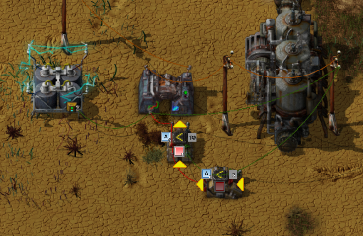
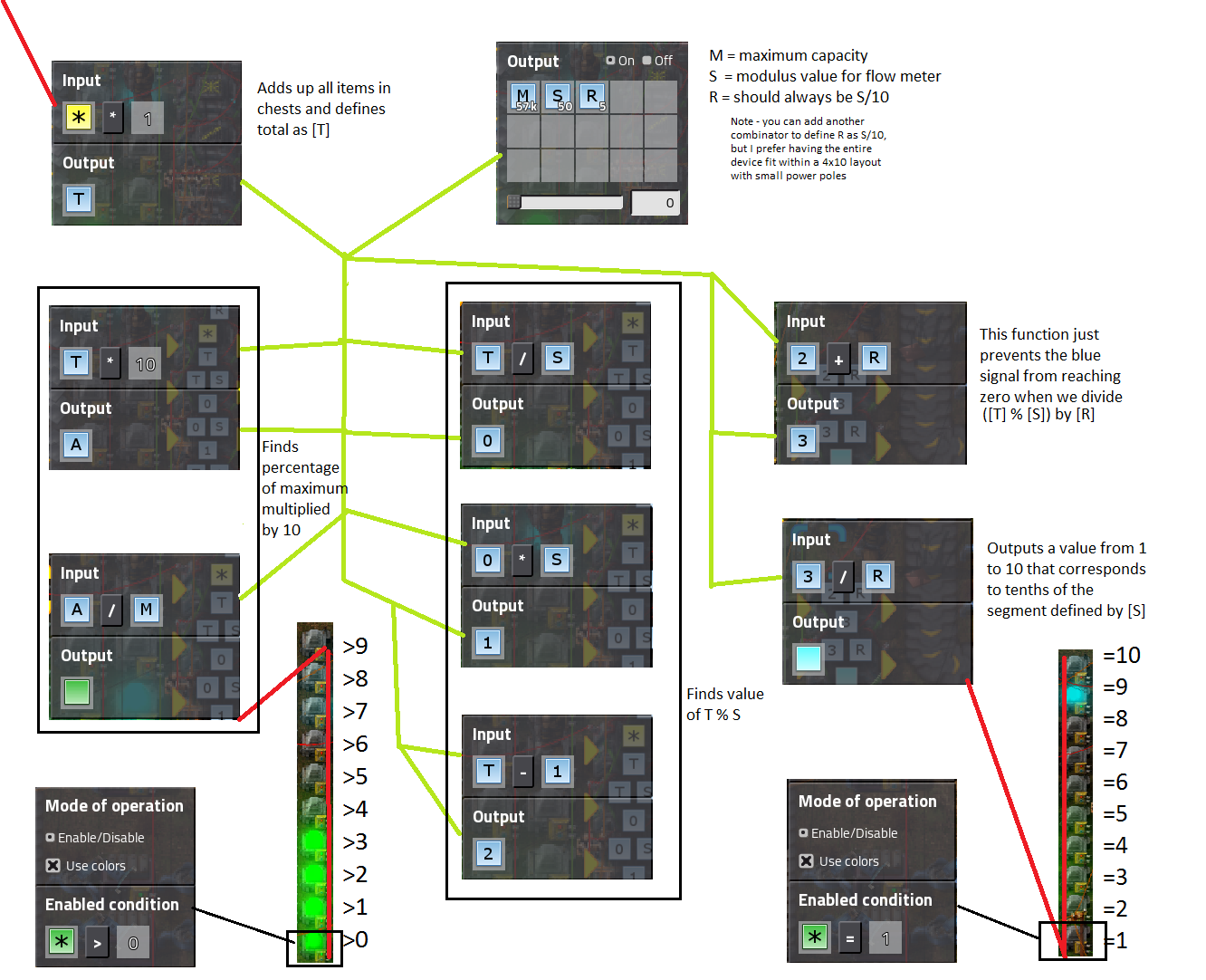
This is how it looks in my map (I kept the original resolution, sorry for the size, that are mac screenshoots with retina display, you need eventually to reduce to 50%)
Screenshots
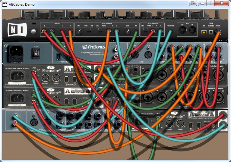
I quote from the thread:So I tried to analyze what really is needed to improve the circuit network, that a player is enabled to understand it and keep it understandable for himself. Most of the issues you can see in the pictures above:ssilk wrote:Optera wrote:even when I designed something myself I often miss connections in this mess... There should be some form of "logic connection mode" showing at glance all connections and the signals on them, I bet you have a whole collection of requests for something like that.ssilk wrote: I didn't get it to run without that glitch. And after 1.5 hours I gave up to understand how this works.Not your fault. I think this is one of Factorios big, big fails, that it is currently hard to impossible to debug/re-engineer circuit network: you cannot follow the wires. I cannot see, where what is connected.

Maybe we should push this as a an important suggestion? cause I think this hinders really playing with a bit more complex circuits than standard.
- You don't see the connection-points: Is this wire now going into that device or does it just look like?
- Wires overlap. Even with the highlighting this overlapping can be misinterpreted.
- Wires are hard to recognize (Too thin, too pixelated).
- Wires are virtual. You cannot touch them once placed: a) What happens if I remove this wire? Impossible to find out, cause you cannot interact with a wire. b) Shit I have made the wrong connection. Where is the UNDO-Key?
- You don't see the signal flow: This output has changed and now that is the new value. Now stop simulation! When this signal goes into this device it will change it's value like so. Ah! But: Unable to debug step by step.
- The handling is a mess: In reality I would make a prototype first. And I don't want to keep an eye on the number of wires, combinators, poles, etc. I just want to plan it first, then prototype it. Placing and mounting of the circuit is a completely different task.
So I mean it is clear, that the circuit network as it is, cannot be used well to share semi-complex circuit blueprints, cause the person, that uses it is sometimes not able to engineer it. He needs to look like a handicapped person on the wires: he cannot touch them.
What is needed to improve this?
- As Optera already mentioned: A "logic connection mode":
You see the wires and devices very schematic and especially you see, where the wires connect.
- Also some kind of commentary:
- Wires needs to be handled with the mouse and can be moved around:
You can grab the wires on both ends and plug it into a different plug/device...
- You need to see, what's going on IN the wire. Now you need to place a pole anywhere and connect the circuit with a wire.
- A prototyping mode would be super-cool: I want some kind of empty surface/edit-mode where I can place any device and wire as I like it and when finished I can drag everything to the right place and orientation, and place that as ghosts.
- And vice versa: Copy a part of the world into this surface/edit-mode and edit it. See above.
- A debug mode would be perfect.