Page 4 of 4
Re: Highlight Color of Circuit Signal based on wire type in Combinator HUD
Posted: Mon Jan 03, 2022 8:58 pm
by FuryoftheStars
Afaik (which isn't much with circuits), signals coming into combinators are combined regardless of wire color and will transmit the same signal out on any connected wire, regardless if the input was originally red and the output is green or vice versa. So, if I'm understanding this request correctly, it would have no use?
If I'm not understanding correctly, I need more details. Maybe pic mockups.
Re: Separate signals to/from red and green wires
Posted: Tue Jan 04, 2022 12:42 am
by ssilk
merged with existing topic
Re: Highlight Color of Circuit Signal based on wire type in Combinator HUD
Posted: Tue Jan 04, 2022 3:01 pm
by SakretonTheSecond
FuryoftheStars wrote: ↑Mon Jan 03, 2022 8:58 pm
Afaik (which isn't much with circuits), signals coming into combinators are combined regardless of wire color and will transmit the same signal out on any connected wire, regardless if the input was originally red and the output is green or vice versa. So, if I'm understanding this request correctly, it would have no use?
If I'm not understanding correctly, I need more details. Maybe pic mockups.
From the pure technical side it has no use that is correct, but if you have many signals from both wires connected to a combinator its hard to separate which signals comes from which wire. It would just be easier to look at them and not have to connect a powerpole to know which signal comes from which wire.
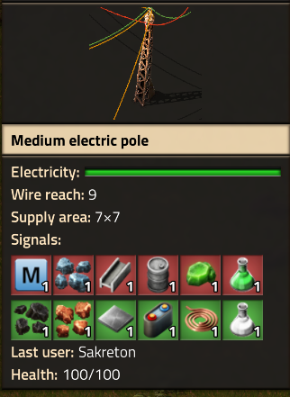
- powerpole.png (112.04 KiB) Viewed 2607 times
Those are the signals connected to a combinator,
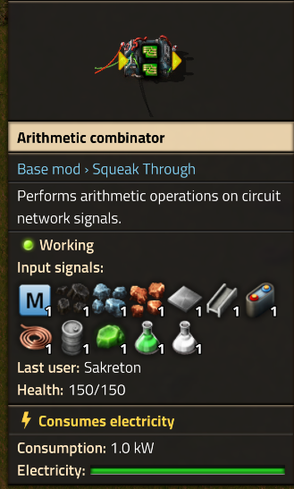
- combold.png (144.03 KiB) Viewed 2607 times
This is how it looks right now,
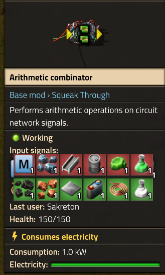
- combnew.png (132.14 KiB) Viewed 2607 times
This is my suggestion. Not very good editing but you get the point.
EDIT:
Of course i should work exactly the same as before just highlight the wire color in the UI
Re: Highlight Color of Circuit Signal based on wire type in Combinator HUD
Posted: Tue Jan 04, 2022 4:17 pm
by Pi-C
SakretonTheSecond wrote: ↑Tue Jan 04, 2022 3:01 pm
From the pure technical side it has no use that is correct, but if you have many signals from both wires connected to a combinator its hard to separate which signals comes from which wire. It would just be easier to look at them and not have to connect a powerpole to know which signal comes from which wire.
Could be useful, but also makes things more complicated. In all the images you've shown, red and green wires carry different signals. Your idea works well in this case. But imagine there were signals of the same kind on both wires (e.g. "iron-ore" = 1 on red and "iron-ore" = 2 on green). On entering the combinator, this would currently be combined to "iron-ore" = 3. That's easy to read, and only one icon needs to be displayed -- while you would not show the total amount, and must display two icons for the same signal.
Adding the amounts of signals from red and green may be quite a chore if you have, say, 10 or 20 signals on each wire. I'd prefer to get the summed values in most cases. However, seeing what exactly is on each wire can be extremely helpful for debugging circuits. I think it would be better to add an optional debugging mode (perhaps it could even be toggled per combinator?) where the incoming signals are shown as you've suggested, but leave the default display as it is.
Re: Highlight Color of Circuit Signal based on wire type in Combinator HUD
Posted: Tue Jan 04, 2022 5:00 pm
by SakretonTheSecond
Pi-C wrote: ↑Tue Jan 04, 2022 4:17 pm
SakretonTheSecond wrote: ↑Tue Jan 04, 2022 3:01 pm
From the pure technical side it has no use that is correct, but if you have many signals from both wires connected to a combinator its hard to separate which signals comes from which wire. It would just be easier to look at them and not have to connect a powerpole to know which signal comes from which wire.
Could be useful, but also makes things more complicated. In all the images you've shown, red and green wires carry different signals. Your idea works well in this case. But imagine there were signals of the same kind on both wires (e.g. "iron-ore" = 1 on red and "iron-ore" = 2 on green). On entering the combinator, this would currently be combined to "iron-ore" = 3. That's easy to read, and only one icon needs to be displayed -- while you would not show the total amount, and must display two icons for the same signal.
Adding the amounts of signals from red and green may be quite a chore if you have, say, 10 or 20 signals on each wire. I'd prefer to get the summed values in most cases. However, seeing what exactly is on each wire can be extremely helpful for debugging circuits. I think it would be better to add an optional debugging mode (perhaps it could even be toggled per combinator?) where the incoming signals are shown as you've suggested, but leave the default display as it is.
If that is possible that would be nice, toggled off by default to avoid conflicts. If signals "overlap" remove its background colour, or add another one.
Re: Highlight Color of Circuit Signal based on wire type in Combinator HUD
Posted: Tue Jan 04, 2022 6:41 pm
by FuryoftheStars
SakretonTheSecond wrote: ↑Tue Jan 04, 2022 3:01 pm
FuryoftheStars wrote: ↑Mon Jan 03, 2022 8:58 pm
Afaik (which isn't much with circuits), signals coming into combinators are combined regardless of wire color and will transmit the same signal out on any connected wire, regardless if the input was originally red and the output is green or vice versa. So, if I'm understanding this request correctly, it would have no use?
If I'm not understanding correctly, I need more details. Maybe pic mockups.
From the pure technical side it has no use that is correct, but if you have many signals from both wires connected to a combinator its hard to separate which signals comes from which wire. It would just be easier to look at them and not have to connect a powerpole to know which signal comes from which wire.
powerpole.png
Those are the signals connected to a combinator,
combold.png
This is how it looks right now,
combnew.png
This is my suggestion. Not very good editing but you get the point.
EDIT:
Of course i should work exactly the same as before just highlight the wire color in the UI
Yeah, ok, so I did understand you correctly. Pi-C summed up my thoughts on this exactly and proposed a nice solution.
Pi-C wrote: ↑Tue Jan 04, 2022 4:17 pm
SakretonTheSecond wrote: ↑Tue Jan 04, 2022 3:01 pm
From the pure technical side it has no use that is correct, but if you have many signals from both wires connected to a combinator its hard to separate which signals comes from which wire. It would just be easier to look at them and not have to connect a powerpole to know which signal comes from which wire.
Could be useful, but also makes things more complicated. In all the images you've shown, red and green wires carry different signals. Your idea works well in this case. But imagine there were signals of the same kind on both wires (e.g. "iron-ore" = 1 on red and "iron-ore" = 2 on green). On entering the combinator, this would currently be combined to "iron-ore" = 3. That's easy to read, and only one icon needs to be displayed -- while you would not show the total amount, and must display two icons for the same signal.
Adding the amounts of signals from red and green may be quite a chore if you have, say, 10 or 20 signals on each wire. I'd prefer to get the summed values in most cases. However, seeing what exactly is on each wire can be extremely helpful for debugging circuits. I think it would be better to add an optional debugging mode (perhaps it could even be toggled per combinator?) where the incoming signals are shown as you've suggested, but leave the default display as it is.
Re: Separate signals to/from red and green wires
Posted: Wed Jan 05, 2022 12:47 am
by ssilk
I would appreciate seeing the signals separately. And at the same time I think this isn’t the right method to see that.
The problem is on a more global level, you want to see, what’s going on. That’s not only inside of the combinators, but also in the inserters, lamps etc.
It wouldn’t make much sense to change this only for combinators, but I have also no clever idea how to make this suggestion better.

Re: Highlight Color of Circuit Signal based on wire type in Combinator HUD
Posted: Mon Aug 29, 2022 10:21 am
by mrvn
Pi-C wrote: ↑Tue Jan 04, 2022 4:17 pm
SakretonTheSecond wrote: ↑Tue Jan 04, 2022 3:01 pm
From the pure technical side it has no use that is correct, but if you have many signals from both wires connected to a combinator its hard to separate which signals comes from which wire. It would just be easier to look at them and not have to connect a powerpole to know which signal comes from which wire.
Could be useful, but also makes things more complicated. In all the images you've shown, red and green wires carry different signals. Your idea works well in this case. But imagine there were signals of the same kind on both wires (e.g. "iron-ore" = 1 on red and "iron-ore" = 2 on green). On entering the combinator, this would currently be combined to "iron-ore" = 3. That's easy to read, and only one icon needs to be displayed -- while you would not show the total amount, and must display two icons for the same signal.
Adding the amounts of signals from red and green may be quite a chore if you have, say, 10 or 20 signals on each wire. I'd prefer to get the summed values in most cases. However, seeing what exactly is on each wire can be extremely helpful for debugging circuits. I think it would be better to add an optional debugging mode (perhaps it could even be toggled per combinator?) where the incoming signals are shown as you've suggested, but leave the default display as it is.
Each tile could be back filled red/green in amounts proportional to the signal. Although that poses a problem if they have different signs. So maybe proportional to their absolute values. And you would have to show "0" signals, like -5 coal green + 5 coal red = 0 coal (half green / half red).
Re: Separate signals to/from red and green wires
Posted: Wed Aug 31, 2022 6:25 am
by ssilk
WTF.

-10 green coal + 5 red coal is then -5 coal (75% green, 25% red). Mathematicaly interesting to calculate with this.

Re: Separate signals to/from red and green wires
Posted: Wed Aug 31, 2022 9:24 am
by mrvn
I would have calculated that as 66% / 33% because it's a 10:5 ratio.
Re: Separate signals to/from red and green wires
Posted: Fri Sep 02, 2022 11:50 pm
by ssilk
Still interesting… it could be seen as 3-dimensional vector (value, red part, green part). But I have no idea what to do with this…
Selectable wire colors fir inserter input/output
Posted: Thu Jun 06, 2024 6:22 pm
by spacehitchhiker42
TL;DR
Similarly to to the "decider combinator 2.0" from FF#384, make red and green selectable as inputs or outputs for inserters
What ?
Basic QOL improvement to allow users to select which color of wire the inserter reads its filters from, or outputs its contents to.
Why ?
This will allow circuit designs to separate command signals (set-filters) from feedback signals (read-contents). This will prevent a read-contents signal from inadvertently causing other inserters to insert unwanted items.
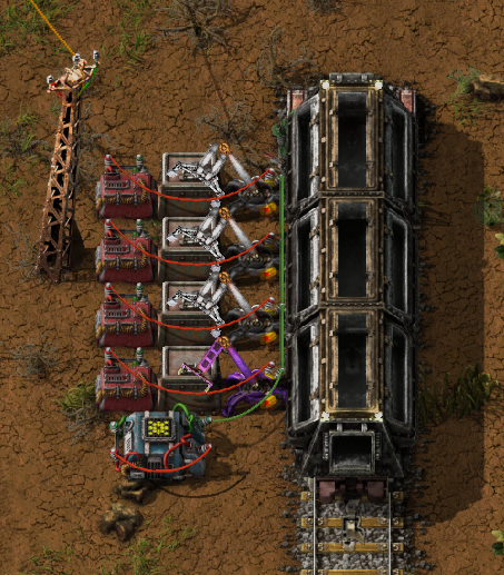
- inserters.png (483.93 KiB) Viewed 1055 times
In this example, each inserter is separately controlled by the red lines, but the green line is used as a common feedback. Without this enhancement, feedback from one inserter is interpreted as a filter command on another. With very fast modded inserters, an inserter can interpret its own feedback signal as a command and become stuck inserting.
Re: Selectable wire colors fir inserter input/output
Posted: Thu Jun 06, 2024 10:54 pm
by Illiander42
Honestly, can we just make this fully general?
ALL circuit connection options can be selected to either red, green or both.
Re: Selectable wire colors fir inserter input/output
Posted: Fri Jun 07, 2024 1:11 am
by mmmPI
but then someone will want to connect a red wire for ouput and a red wire for input, but another one not the same... no ?
and this would be problematic for entity that are only 1 tile of surface or make it difficult to plug properly the wire on the half tile or something.
I'm not against the suggestion per say but i think the expansion will show quite the rework of circuits and may alter how to consider some propositions like this one.
Re: Selectable wire colors fir inserter input/output
Posted: Sat Jun 08, 2024 12:09 am
by spacehitchhiker42
Illiander42 wrote: ↑Thu Jun 06, 2024 10:54 pm
Honestly, can we just make this fully general?
ALL circuit connection options can be selected to either red, green or both.
I agree.
mmmPI wrote: ↑Fri Jun 07, 2024 1:11 am
but then someone will want to connect a red wire for ouput and a red wire for input, but another one not the same... no ?
and this would be problematic for entity that are only 1 tile of surface or make it difficult to plug properly the wire on the half tile or something.
I don't really think you'd need to make separate input and outpoints like the new combinators are going to have. Being able to use a red wire for output and a red wire for input
would be nice, but just being able to select red as input and green as output (or vice versa) wouldn't really be too constraining. If you needed an output on the same color as your input, you could use a combinator as a diode to switch the colors. You'd only need one diode for a bank of combinators, as opposed to a diode for input and one for output for each pair.
Re: Selectable wire colors fir inserter input/output
Posted: Sat Jun 08, 2024 12:23 am
by regular_human
you can actually already do this, in a hacky kinda way. I use it for my Science River blueprint -
(paste it in a creative map and set all trains to auto to get it started)
Take a look at the huge bank of stack filter inserters on the left side, the green wire sets the filter and the red wire reads hand contents. In order to prevent the red wire from interfering with the green wire settings, the green wire also has a constant combinator of the signals that red wire *might* see set to -1,000. Negative signal values do not set filters, and this is more than the red wire signal quantity will ever exceed. Then the combinator that rotates the filter-setting signal is multiplied by 10,000 on the green wire. So the sum total of red and green wires on any given inserter is 6 science packs that are negative, and one very high signal that sets the filter.
Re: Selectable wire colors fir inserter input/output
Posted: Sat Jun 08, 2024 12:53 am
by mmmPI
Cool blueprint x). You may need to explain how the requester chest get their request too, just to make sure, because it seem a bit like magic

It look like it's kept in 2 constant combinator that are allowed to send signal only when a train is there ?
spacehitchhiker42 wrote: ↑Sat Jun 08, 2024 12:09 am
I don't really think you'd need to make separate input and outpoints like the new combinators are going to have. Being able to use a red wire for output and a red wire for input
would be nice, but just being able to select red as input and green as output (or vice versa) wouldn't really be too constraining. If you needed an output on the same color as your input, you could use a combinator as a diode to switch the colors. You'd only need one diode for a bank of combinators, as opposed to a diode for input and one for output for each pair.
I can hear that, i was asking the question, now i have an answer
i'm not sure i can properly assess it though, i understand better the proposition, but it still has to be weighted against "what will be possible with the expansion" for me to give opinion rather than just ask question.
Re: Selectable wire colors fir inserter input/output
Posted: Sat Jun 08, 2024 1:04 am
by regular_human
mmmPI wrote: ↑Sat Jun 08, 2024 12:53 am
You may need to explain how the requester chest get their request too, just to make sure, because it seem a bit like magic
My super secret tech. It's a circuit that balances contents of requester chests based on total contents of the logistic network. When the inserters offload the science packs from the train into providers, they are counted and put into a memory cell. The contents of the memory cell are divided by the total number of requester chests (kinda, chests that have 2 inserters pulling from them are counted twice), and those are the signals that set the requests. The red wire on the white inserters subtract from the memory cell, so the memory cell is keeping track of the total contents of the requesters without being able to read their contents. It causes all chests to be delivered to equally when the train arrives instead of the bots prioritizing nearby chests.
Re: Separate signals to/from red and green wires
Posted: Sun Jun 09, 2024 7:24 am
by Koub
[Koub] Merged into an older thread with the same suggestion.
There are also several other suggestions that don't focus specifically on the ability to distinguish signals based on what wire color they're on, but kind of builds upon that feature :
viewtopic.php?f=6&t=31438
viewtopic.php?f=6&t=94715
Re: Selectable wire colors fir inserter input/output
Posted: Tue Jun 11, 2024 10:53 pm
by mmmPI
regular_human wrote: ↑Sat Jun 08, 2024 1:04 am
My super secret tech. It's a circuit that balances contents of requester chests based on total contents of the logistic network. When the inserters offload the science packs from the train into providers, they are counted and put into a memory cell. The contents of the memory cell are divided by the total number of requester chests (kinda, chests that have 2 inserters pulling from them are counted twice), and those are the signals that set the requests. The red wire on the white inserters subtract from the memory cell, so the memory cell is keeping track of the total contents of the requesters without being able to read their contents. It causes all chests to be delivered to equally when the train arrives instead of the bots prioritizing nearby chests.
Thanks for the explanation, i'm afraid it's not longer secret, it's now your public super tech imo, it's remains "super"