Page 1 of 5
Final (Maxed) Designs
Posted: Fri May 29, 2015 5:44 pm
by DerivePi
Updated 1-2017 and revised
This is for posting final maxed out designs.
The rule is that at least one input or output belt/pipe must utilize a full (40 item per second) express belt or a full (60 items per second) pipe. Any expansion, would require a duplicate instance of the setup.
As an example, here is a maxed out basic circuit production schematic (note the maxed out 40 iron plate in and 40 circuits out), picture and blueprint screen:
SCHEMATIC
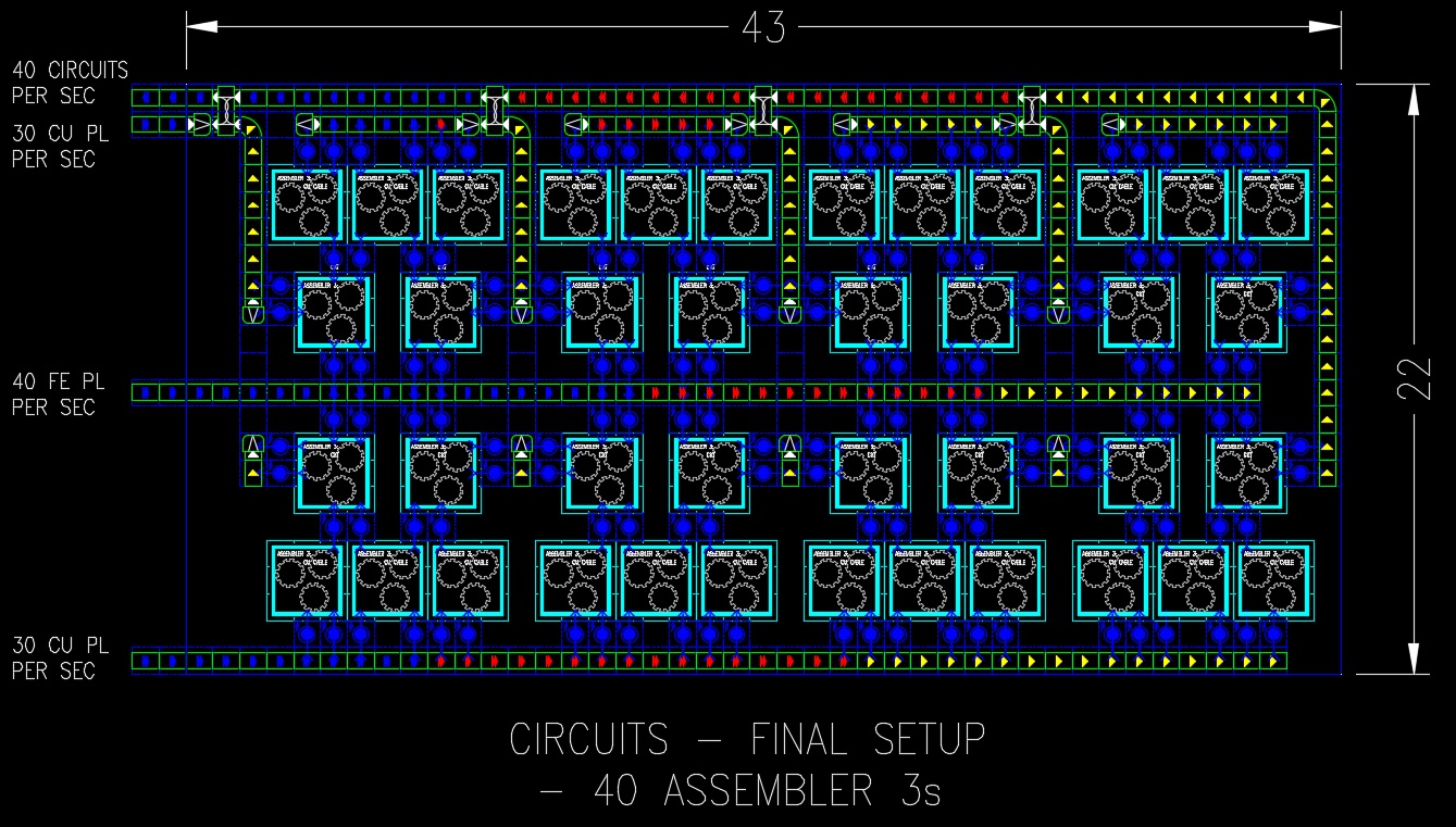
- CIRCUIT-FINAL.jpg (404.8 KiB) Viewed 35023 times
IN-GAME
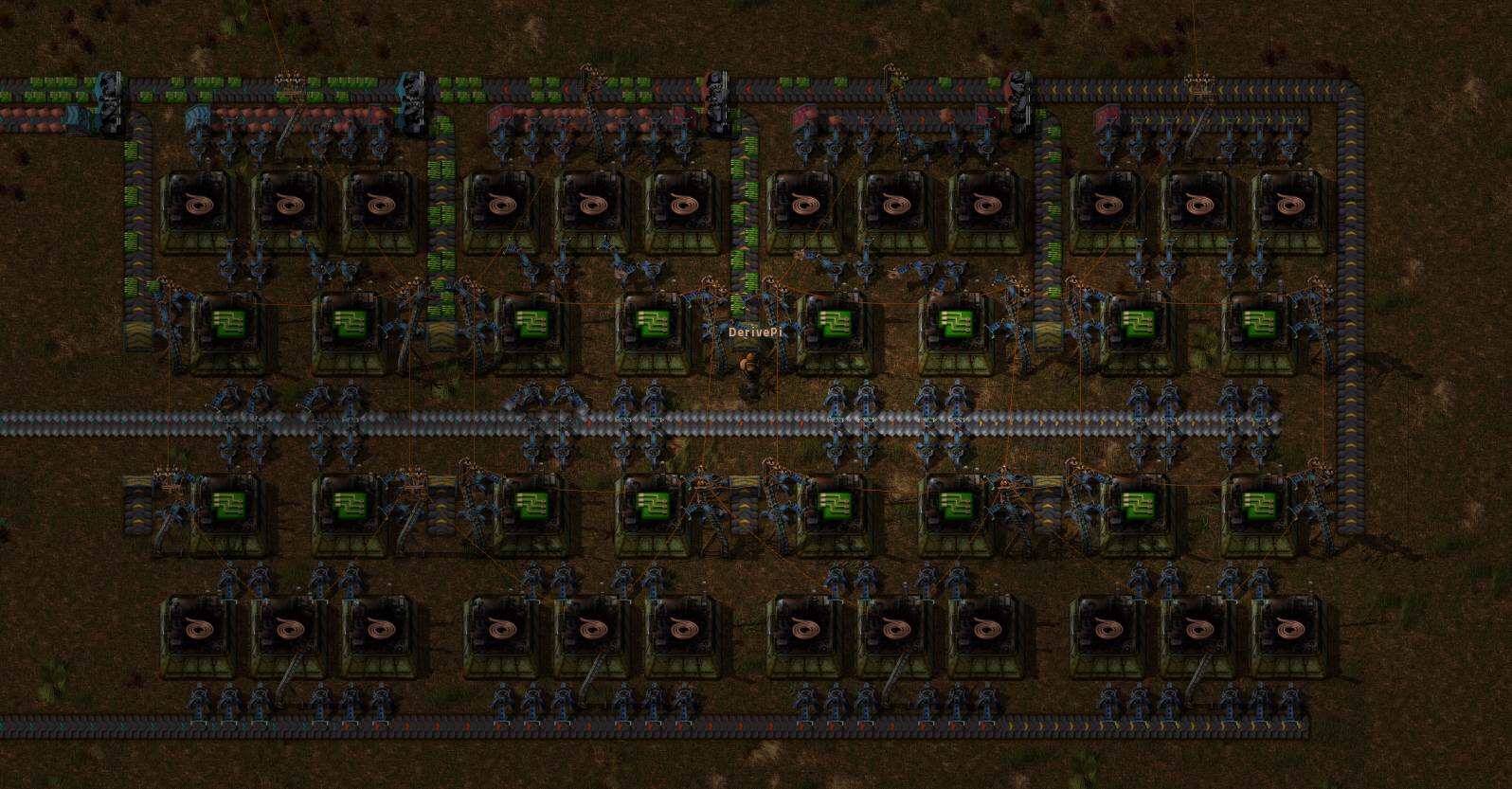
- circuit-final2.png (2.47 MiB) Viewed 35038 times
Re: Final (Maxed) Designs
Posted: Sun May 31, 2015 12:59 am
by Zhall
Why not just take a screenshot from ingame?
Re: Final (Maxed) Designs
Posted: Sun May 31, 2015 5:51 am
by PiggyWhiskey
Also why not use "Copper" and "Iron" instead of CU and FE. Not everyone knows or wants to use the Symbols.
Re: Final (Maxed) Designs
Posted: Sun May 31, 2015 8:33 am
by Trev_lite
Cu and Fe are easy to understand but ckt took sometime to understand.
Re: Final (Maxed) Designs
Posted: Mon Jun 01, 2015 5:47 pm
by DerivePi
This is my concept for a maxed out Advanced Circuit facility with 96 advanced circuit assemblers and 12 copper wire assemblers.
- ADV CKT.gif (135.88 KiB) Viewed 47687 times
Re: Final (Maxed) Designs
Posted: Tue Jun 02, 2015 3:03 am
by PiggyWhiskey
DerivePi wrote:This is my concept for a maxed out Advanced Circuit facility with 96 advanced circuit assemblers and 12 copper wire assemblers.
ADV CKT.gif
2 Questions.
Why don't you take an in-game screenshot? easier to see.
What program do you use for that?
Re: Final (Maxed) Designs
Posted: Tue Jun 02, 2015 5:18 am
by Koub
I'ts done with Autocad.
And is so much badass : every Factorio player can screenshot Factorio, but not everyone can make an Autocad plan.
Btw : if I had Autocad at work, I could make such plans at work, and still be congratulated by my boss for my hard dedication to my work

Re: Final (Maxed) Designs
Posted: Wed Jun 03, 2015 3:19 am
by york2dx48
Why have you got the outputs on two different sides?
Re: Final (Maxed) Designs
Posted: Wed Jun 03, 2015 3:25 am
by york2dx48
york2dx48 wrote:Why have you got the outputs on two different sides?
No sorry I read it wrong. Forgot you need iron...
Re: Final (Maxed) Designs
Posted: Wed Jun 03, 2015 10:24 am
by york2dx48
That's how a friend has shown it to me. ( just ignore the storage chest next to the belt)
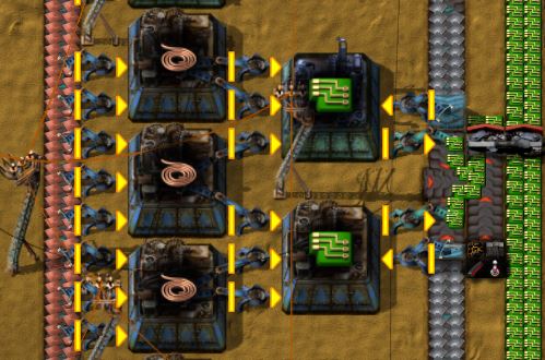
- green circuits.JPG (53.15 KiB) Viewed 47451 times
Re: Final (Maxed) Designs
Posted: Wed Jun 03, 2015 12:35 pm
by dee-
What qualifies as a "Final (Maxed) Design" ?
Re: Final (Maxed) Designs
Posted: Wed Jun 03, 2015 12:40 pm
by ratchetfreak
dee- wrote:What qualifies as a "Final (Maxed) Design" ?
DerivePi wrote:
The rule is that at least one input or output belt/pipe must utilize a full (30 item per second) express belt or a full (60 items per second) pipe. Any expansion, would require a duplicate instance of the setup.
Re: Final (Maxed) Designs
Posted: Wed Jun 03, 2015 12:47 pm
by dee-
oh boy. my bad ^^'
I began skipping posts from DerivePi when he posts screenshots in them as their intense garish colors give me eye strains and I find no joy in decyphering his schematics, which I feel is a loss and pity, but it can't be helped. And as a technical draftsman I *WORKED* with CAD programs...
Maybe I should at least always read the OP

Re: Final (Maxed) Designs
Posted: Thu Jun 04, 2015 8:38 am
by RoddyVR
york2dx48 wrote:That's how a friend has shown it to me. ( just ignore the storage chest next to the belt)
green circuits.JPG
Add 1 more fast inserter for iron to each circuit assembly. i will bet that the choke point in this setup will be the inserters taking iron, if you add one more each, the choke point will be the inserter taking circuits out of the assemblies.
Re: Final (Maxed) Designs
Posted: Thu Jun 04, 2015 12:28 pm
by DerivePi
RoddyVR wrote:york2dx48 wrote:That's how a friend has shown it to me. ( just ignore the storage chest next to the belt)
green circuits.JPG
Add 1 more fast inserter for iron to each circuit assembly. i will bet that the choke point in this setup will be the inserters taking iron, if you add one more each, the choke point will be the inserter taking circuits out of the assemblies.
Actually, there are 3 mistakes with my circuit layout schematic:
1. There need to be more inserters from the copper plate belt into the wire assemblers
2. You can't fully load an express belt with inserters. I need to add branch belts and splitters to combine.
3. The colors are too garish. Not Feng Shui at all!

The iron plate inserters should be fine. The circuit assemblers use 2.5 iron plates per second and the 2 inserters are capable of 4.2 per second.
Re: Final (Maxed) Designs
Posted: Thu Jun 11, 2015 11:20 am
by Batsma2
DerivePi wrote:RoddyVR wrote:york2dx48 wrote:That's how a friend has shown it to me. ( just ignore the storage chest next to the belt)
Actually, there are 3 mistakes with my circuit layout schematic:
1. There need to be more inserters from the copper plate belt into the wire assemblers
2. You can't fully load an express belt with inserters. I need to add branch belts and splitters to combine.
3. The colors are too garish. Not Feng Shui at all!
The iron plate inserters should be fine. The circuit assemblers use 2.5 iron plates per second and the 2 inserters are capable of 4.2 per second.
if you don't mind i'd like to add a fourth issue, you have 6 out of nine circuit assemblers unloading to 1 side of the belt system, this necessitates a belt balancer on the green circuit line which is offcourse sub-optimal.
I really like the " cheapness" of the design concerning the use of red and yellow belts, this is an integral part of optimizing.
if you'd like I can set you a challenge as well, try and build an optimized design for building all belt types efficiently. although you might just want them to unload in logistics chests for your bot, the supply lines can be quite tricky.
Re: Final (Maxed) Designs
Posted: Thu Jun 11, 2015 12:41 pm
by DerivePi
DerivePi wrote:Actually, there are 3 mistakes with my circuit layout schematic:
1. There need to be more inserters from the copper plate belt into the wire assemblers
2. You can't fully load an express belt with inserters. I need to add branch belts and splitters to combine.
3. The colors are too garish. Not Feng Shui at all!
1. added 2nd fast inserter to feed copper cable assemblers
2. added 2nd belt for exporting circuits with balancer in the middle.
3. changed the background to "salmon" for this one time only
- final ckt.gif (289.89 KiB) Viewed 42832 times
Re: Final (Maxed) Designs
Posted: Thu Jun 11, 2015 2:38 pm
by dee-

Quick - where are my sunglasses?
I hope you take my remark in good humor because in retrospect I think I worded it too negative and harsh. Hopefully no bad feelings?

Keep em coming!

Re: Final (Maxed) Designs
Posted: Thu Jun 11, 2015 2:45 pm
by starholme
Salmon? First time my eyes have ever bled while looking at a fish.
Re: Final (Maxed) Designs
Posted: Thu Jun 11, 2015 4:44 pm
by Pajamas
These are great, Pi. Thank You! Any others?
