Configurable buffer capacity/flow meters

This board is to show, discuss and archive useful combinator- and logic-creations.
Smart triggering, counters and sensors, useful circuitry, switching as an art :), computers.
Please provide if possible always a blueprint of your creation.
Post Reply
regular_human
Manual Inserter
Manual Inserter
Posts: 4
Joined: Wed Apr 05, 2017 12:50 am
Contact:

Configurable buffer capacity/flow meters

Post by regular_human »

Image

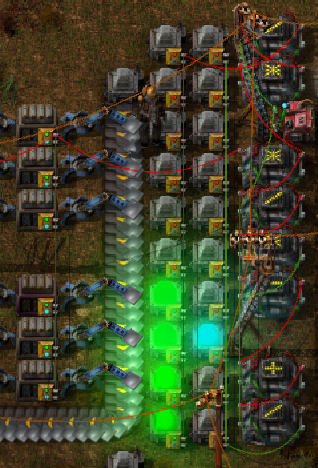
Hi everybody, I made this thing with combinators that I'm really proud of. This device gives you two 10-block meters that show the capacity of the buffer as a percentage of its maximum, and at what rate materials are flowing into or out of the buffer. Here's what it looks like in action:

Buffer increasing - https://gfycat.com/GlaringCommonFlee
Buffer decreasing - https://gfycat.com/FlatChubbyKillerwhale

These clips are showing that the iron buffer is at least 40% full, and each time the blue dot moves indicates a change of 5 units. This number is configurable so that you can smooth out the motion of the flow meter for very high throughput buffers.

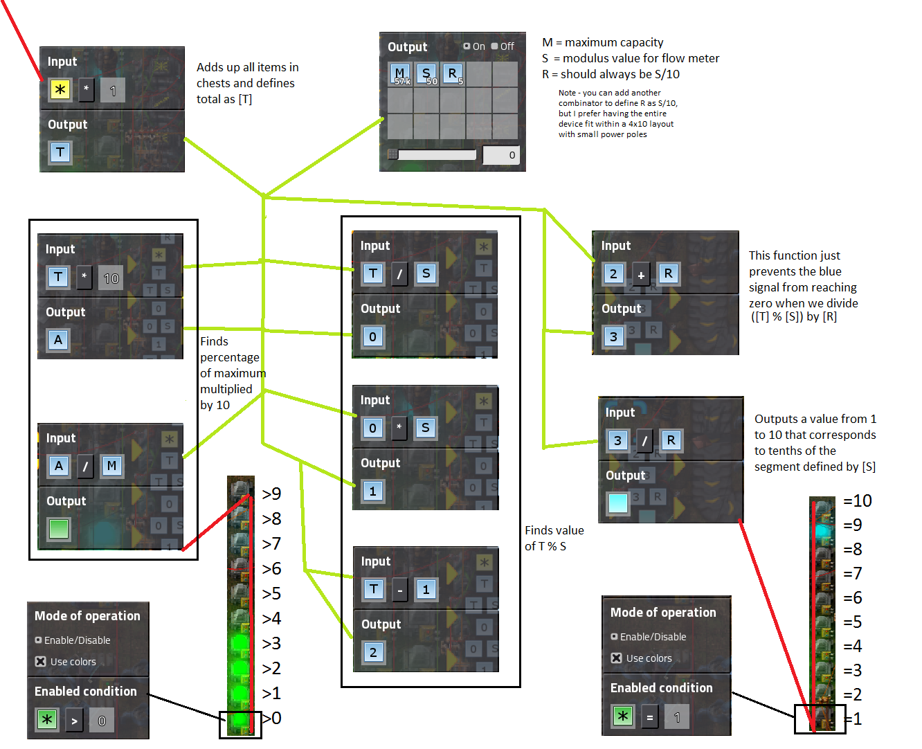
This device uses 8 arithmetic and 1 constant combinator. It's easy to cut and paste since there's only one wire that needs to be connected to the chests for everything to work perfectly, and then you can modify the maximum capacity value and flow resolution on the constant combinator depending on what you're monitoring.

Here is a diagram I put together in paint to show how everything is connected, I tried as hard as I could to make it not look like doodoo. Please let me know if anything is unclear and I'll be happy to clarify (blueprint below) -Image
Blueprint

Permittivity
Inserter
Inserter
Posts: 33
Joined: Sun Mar 26, 2017 10:24 pm
Contact:

Re: Configurable buffer capacity/flow meters

Post by Permittivity »

Thanks for sharing. As you have discovered, you can use the limitations of signals, such as their truncation to integer values, to allow advanced operations like modulus.

One of the next concepts to master is the fact that the circuit network updates inputs->outputs only once per tick, thus we can create circuits with clocks. I've thrown together a little example showing how you can utilize this to compute a signal representing the flow rate from your chests.
Circuit.jpg
Circuit.jpg (330.57 KiB) Viewed 1835 times
The clock is pretty simple. The constant combinatory means that the clock signal always has a value of at least one. Then, on each tick, if the clock signal is less than 300 the decider combinator takes the clock value and makes it an input for the following tick. All inputs are added, so the total input for the next tick is equal to the current clock signal plus the one from the constant combinator. Thus you get a clock that counts up by one each tick until it reaches 300 after which it starts back over at one.

The memory latches similarly depend on the fact that circuits are only updated once per tick. Each time the clock strobes, the arithmetic combinator sets the output of the following tick to the count of its input. For all other ticks, the decider combinator sets the output of the following tick to be the same as the output of this tick.

Post Reply

Return to “Combinator Creations”