Page 1 of 6
Re: Combinator Contraptions
Posted: Thu Mar 03, 2016 11:41 pm
by XKnight
DaveMcW wrote:
That is pretty easy.
Set up 2 memory cells, 1 with all signals, 1 with all negative signals (each * -1).
Each tick, use the ANY signal to pick one signal from each memory cell. Then feed it to the opposite memory cell to delete it. Also feed it to the opposite ANY combinator to avoid any delays.
Small problem... If you are using ANY signal you should specify output signal type, and without correct type you won't be able to sum signal with opposite memory cell. Am I missing something?
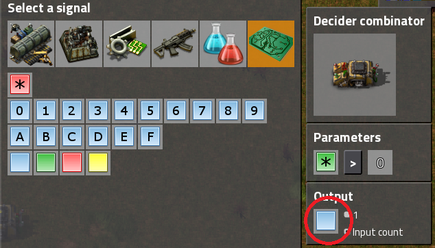
- 1.png (246.05 KiB) Viewed 31649 times
Dr. Walrus wrote: Getting it down to one tick between each output might be hard but not impossible.
That's why this is a challenge.
Dr. Walrus wrote: Also would the signals all be positive?
Yep.
Re: Combinator Contraptions
Posted: Fri Mar 04, 2016 12:58 am
by DaveMcW
Doh, that is what I get for posting without testing.

Re: Combinator Contraptions
Posted: Fri Mar 04, 2016 2:16 am
by Dr. Walrus
DaveMcW wrote:
That is pretty easy.
Set up 2 memory cells, 1 with all signals, 1 with all negative signals (each * -1).
Each tick, use the ANY signal to pick one signal from each memory cell. Then feed it to the opposite memory cell to delete it. Also feed it to the opposite ANY combinator to avoid any delays.
I don't think it's quite so easy as that, because when you use a combinator with the ANY signal you are only getting the value of the signal you want. To get the actual type of signal and value you'll need to run it through another combinator to get the signal with the same value. And you can't erase the old signal from memory until you're done with the second combinator. So unless I'm missing something I'm pretty sure it will take 2 ticks. Please correct me if I'm wrong.
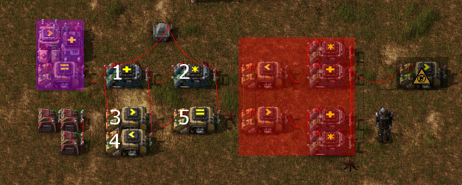
I've got a start to a solution that you might be able to work on. This one takes a 1 tick long signal of a bunch of items and outputs them in order every
2 ticks. It's limited to only positive or only negative numbers and all of their values must be different.
The purple highlighted section just turns the output from the constant combinators into a 1 or 2 tick signal.
The red highlighted section converts negative number outputs into positive numbers and cleans up the signal.
The first signal in order is sent out from combinator 5, and it is erased from the combined signal by combining the wire with the output of combinator 2, which multiplied everything by negative 1. Therefore the second loop will use all negative numbers and the second signal will be output as negative, which is why the output needs to be hooked to a thing that turns negative signals into positive.
*EDIT* I posted this before I saw your guys latest posts. And I just now saw your requirement that the sequence doesn't matter. If that's ok then you can split the input by over/under average and then run both of those through parallel versions of my design, delay one of them by 1 tick, and then reconnect the outputs.
*EDIT 2* I realized that you'd have to split the input by exactly half. So to do that you would need the median, not the average, and I'm not really sure how to calculate the median.
Re: Combinator Contraptions
Posted: Fri Mar 04, 2016 2:41 pm
by piriform
I tried a number of configurations and No Joy. Best can output @2-3 ticks/signal.
DaveMcW's comment led me to investigate the following.
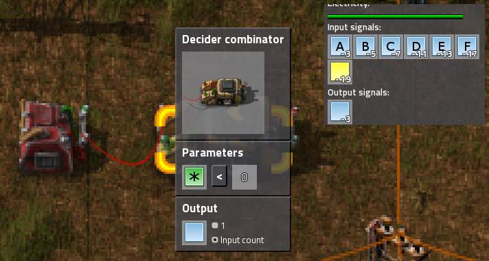
- hmm2.jpg (38.49 KiB) Viewed 31616 times
Interesting, but probably a distraction. Although, if the signals have an upper limit and the signals are subtracted from that limit then inverted???
I'd like to know a bit more about the signal values
a) are values increasing (or can be made) monotonically or at least in some order?
b) Can the set (of signals) be partitioned and treated in parallel?
Re: Combinator Contraptions
Posted: Fri Mar 04, 2016 5:41 pm
by XKnight
piriform wrote:
I'd like to know a bit more about the signal values
a) are values increasing (or can be made) monotonically or at least in some order?
b) Can the set (of signals) be partitioned and treated in parallel?
a) signals don't have any strict order
b) as you wish, but this will be your own implementation detail
Re: Combinator Contraptions
Posted: Sun Mar 06, 2016 9:01 am
by Dr. Walrus
Posted a new contraption, the variable signal delayer. Check it out.
XKnight, did you ever come up with a solution for your challenge? If you split the signals by above and below the median you could do two of those things I posted in parallel, but you would have to know the median in advance, and you wouldn't have as much control over the order the signals came out.
Re: Combinator Contraptions
Posted: Sun Mar 06, 2016 10:06 am
by XKnight
Dr. Walrus wrote:Posted a new contraption, the variable signal delayer. Check it out.
XKnight, did you ever come up with a solution for your challenge? If you split the signals by above and below the median you could do two of those things I posted in parallel, but you would have to know the median in advance, and you wouldn't have as much control over the order the signals came out.
In fact, I found the solution 2 days ago, but it has about 40 combinators (3 ticks first delay) which makes this build quite expensive.
Re: Combinator Contraptions
Posted: Mon Mar 07, 2016 7:26 am
by DaveMcW
Here is a solution with 30 combinators, not counting the loader. Unfortunately it suffers from
this bug, so the timing is a bit messed up. I'm sure it can be optimized further, but I am happy just to get it functional.
It uses my previous strategy, with the added feature of splitting the data set above and below the average. This gives 2 signals every 2 ticks. Since the average is 2 ticks behind, I inject the partial result from the ANYTHING signal directly into the AVERAGE calculation to keep it accurate.
The blueprint is missing the red wire between the constant combinator and the electric pole; add that when the build is complete.
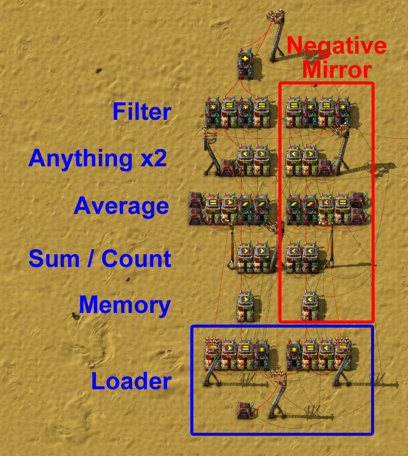
- iterator.jpg (743.71 KiB) Viewed 31529 times
Re: Combinator Contraptions
Posted: Mon Mar 07, 2016 10:40 am
by XKnight
And here is my solution:
- 18 combinators
- 3 ticks first delay (may be reduced to 2 ticks, but this is not so important)
- doesn't use negative mirror, as a result it doesn't suffer from
this bug and any decision that will be made there
- input values should be in range 100...200 (may be increased by changing constant)
- 1.png (706.21 KiB) Viewed 31516 times
Re: Combinator Contraptions
Posted: Mon Mar 07, 2016 11:03 am
by XKnight
DaveMcW wrote:Here is a solution with 30 combinators, not counting the loader. Unfortunately it suffers from
this bug, so the timing is a bit messed up. I'm sure it can be optimized further, but I am happy just to get it functional.
It uses my previous strategy, with the added feature of splitting the data set above and below the average. This gives 2 signals every 2 ticks. Since the average is 2 ticks behind, I inject the partial result from the ANYTHING signal directly into the AVERAGE calculation to keep it accurate.
The blueprint is missing the red wire between the constant combinator and the electric pole; add that when the build is complete.
I found several problems in your build:
Input: your test case;
Also, you loader has a little bit complex mechanic... it sends reduced number of signals each tick, which (in my opinion) is not the same as "send 15 different signals each 15th tick". But it is your decision whether or not to count loader as a part of solver.
By the way, here is my output on your test:
Re: Combinator Contraptions
Posted: Mon Mar 07, 2016 6:23 pm
by DaveMcW
Yes, the bug makes the output incorrect. It is designed for Factorio 0.12.27.

Edit:
Still not fixed.

Maybe Factorio 0.12.28...
Re: Combinator Contraptions
Posted: Thu Mar 10, 2016 10:54 pm
by piriform
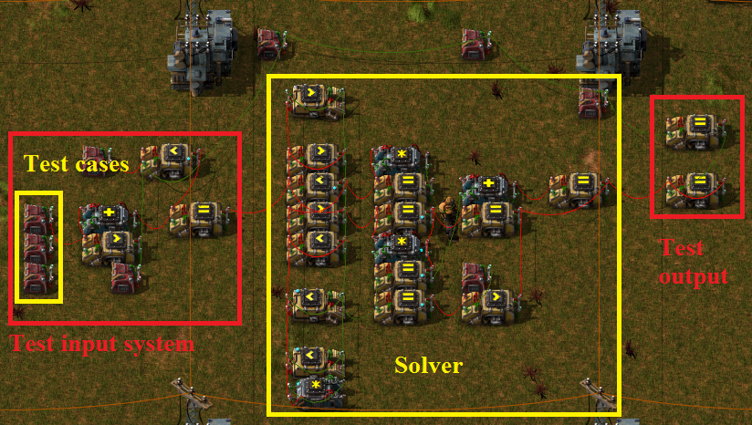
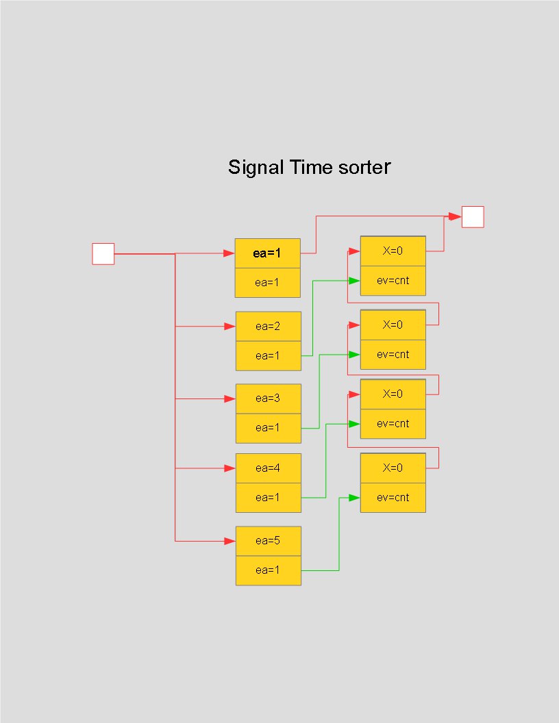
The following is NOT a solution that was asked for, but may be of use to some as it deals with a similar type of a problem. Specifically, how to quickly time sort many signals into relatively few time slots. There are 5 time slots In the diagram, although the circuit can be extended indefinitely provided one is willing to pay for 2 deciders per additional slot.
- sts.jpg (41.09 KiB) Viewed 10598 times
How it works. The signals value correspond to the desired time slot. All the signals are dumped into the sorter in a pulse 1 tick wide. The deciders on the left select all the signals that belong in the desired time slot and inject them into the delay line formed by the deciders on the right.
Re: Combinator Contraptions
Posted: Wed Mar 16, 2016 10:58 am
by Amegatron
Dr. Walrus wrote:This one is a little more specific. It inputs the rising edge of a signal, and outputs it later after being delayed by a custom number of ticks. The tick length of the delay is set by the value of the blue signal in the top-right constant combinator. For this contraption to work properly It has to receive a signal with at least 1 positive number and It can't contain any blue signals. The minimum delay is 5 ticks, and the maximum is 99,999,999 in case you want to input a signal and have it output once you finish college.
Damn, this is what I was looking for. But still I cannot understand how does it work :/ I've already started a topic nearby about delayed pulse generator. Seems your solution could help me. Could you please explain or maybe just post this layout more spaced so I could clearly see all wires?
Re: Combinator Contraptions
Posted: Wed Mar 16, 2016 8:05 pm
by XKnight
Amegatron wrote:Dr. Walrus wrote:This one is a little more specific. It inputs the rising edge of a signal, and outputs it later after being delayed by a custom number of ticks. The tick length of the delay is set by the value of the blue signal in the top-right constant combinator. For this contraption to work properly It has to receive a signal with at least 1 positive number and It can't contain any blue signals. The minimum delay is 5 ticks, and the maximum is 99,999,999 in case you want to input a signal and have it output once you finish college.
Damn, this is what I was looking for. But still I cannot understand how does it work :/ I've already started a topic nearby about delayed pulse generator. Seems your solution could help me. Could you please explain or maybe just post this layout more spaced so I could clearly see all wires?
Your task gave me an idea of interesting challenge:
Re: Combinator Contraptions
Posted: Thu Mar 17, 2016 4:02 pm
by Dr. Walrus
I've been a bit busy with work lately and I'm away from my factorio computer so I'll give you a quick rundown on how it works. IF you are still confused I'll post a complete breakdown in a few days.
The input signal is run through a 1 tick limiter that only outputs the first tick of a signal. It is then run through a memory cell, which is connected to the output. When the input signal passes through the 1 tick limiter it then gets stored in the memory cell and simultaneously starts a clock that goes up by 1 every tick. The clock keeps going up until it hits the user specified value of how many ticks you want to delay the signal. When this happens, simultaneously the memory cell is told to output its contents and clear its memory (which generates a 1 tick pulse for the output) and the clock gets reset.
It's a fairly kludgy design and there's probably better ways to set up the internal logic to reduce the number of combinators.
XKnight wrote:Your task gave me an idea of interesting challenge:
That's quite an interesting challenge again XKnight. In your example, it seems like you would need at least 7 memory cells, one to save the value of each individual tick in the input signal. Waiting a variable amount of time wouldn't be too hard, just affix a blue signal of the value of the input tick to each input and then output when a clock = that signal + user selected delay. However if you wanted to use less memory cells than the number of individual ticks, that would be tricky. You would have to encode your signals somehow so multiple signals could fit on the same combinator. hmmmm... Once again you've given me another idea for my next combinator contraption, but an elegant solution to your challenge eludes me.
Re: Combinator Contraptions
Posted: Thu Mar 17, 2016 7:30 pm
by XKnight
Dr. Walrus wrote:You would have to encode your signals somehow so multiple signals could fit on the same combinator. hmmmm... Once again you've given me another idea for my next combinator contraption, but an elegant solution to your challenge eludes me.
Right direction, keep going!

Re: Combinator Contraptions
Posted: Sat Mar 19, 2016 7:03 pm
by Dr. Walrus
I've just posted a new contraption, The Basic Encoder. It takes any individual signal under 10M and changes it into a single blue signal that contains both the type and value of the signal. This one could be the starting point of a device that allows you to store multiple signals of the same or of different types in one memory cell if you have those signals encode as different item depending on their order.
Re: Combinator Contraptions
Posted: Sat Mar 19, 2016 7:47 pm
by piriform
I could not load blue print due to error: Unknown entity basic-pressure-plate. In the meantime my WAG is that you are using a form of Godelization

.
Re: Combinator Contraptions
Posted: Sun Mar 20, 2016 3:13 pm
by Dr. Walrus
piriform wrote:I could not load blue print due to error: Unknown entity basic-pressure-plate. In the meantime my WAG is that you are using a form of Godelization
.
Oops! Good catch. It's fixed now.
And yes it does use Godel numbering, but only in the most primitive sense of the concept. The amount of the input signal is just converted to blue, and the type of the signal is converted into a number where wooden chest = 1, iron chest = 2, etc. and then multiplied by 10M. When added together the amount of the blue signal contains both the type and amount of the signal without going over the game's 32 bit signed integer limit. Using the true Godel numbering system with the product of a series of primes raised to the numbers you wish to encode would be huge, slow and really cool but would probably go over the integer limit really quickly. And the decoder would require me to build a contraption that calculates the nth root [ x^(1/n)] which is too big of an undertaking for me.
*Edit to avoid double posting*
Since I accidentally included pressure plates in my last contraption, the next contraption is all about pressure plates. The pressure plate stopwatch, for when you want to play factorio at 6:00 but you've got a track meet at 4:30.
Re: Combinator Contraptions
Posted: Thu Apr 14, 2016 4:39 pm
by Black Ice
This is my first attempt at a computer in factorio. It's 256, 5 by 7 displays arranged in a 16 by 16 grid and it can type, by placing copper plates in the "keyboard", do very basic maths and algebra and has some basic memory. Was hoping to put in a game next (chess??) and any advice would be appreciated.

- Computer in Factroio.png (6.82 MiB) Viewed 10293 times