
You can switch it to 32 bit by clicking on "QWORD" to change it to "DWORD".
Minimalist signal filtering device
Re: Minimalist signal filtering device
Efficient inefficient design.

Re: Minimalist signal filtering device
What you're describing (inverting every bit/lamp) is ones complement. To get twos complement you then also need to add 1.mmmPI wrote: ↑Mon Nov 29, 2021 8:24 pmon a joke side : I think i have an idea to replace paper by 32 or 64 lamps. Also i would need a contraption that convert my base 10 number into binary. this way less writing :dTertius wrote: ↑Mon Nov 29, 2021 7:41 pmIf you want to design something that depends on the bit-representation of the values, you need to think in binary values. And you need to know the representation of negative numbers (two's-complement) and why this is used. And if you cannot think in binary (I cannot, too many digits), you need to write all the 32 bits in 0 and 1 on paper and use the paper for thinking.
i have seen couple basic explanation on two's complement, but haven't used much because either no purpose for me personnaly for what i've been doing or maybe when i could use it i didn't recognize it.
It would be the number that is represented by the opposite of the 32 lamps in my idea i think, if a number is represented with 32 lamps on or off, then you imagine the lamp that are on are instead off and vice versa. or you just plug in a unary not gate as pictured on the wiki to every lamp
representations of negative integers
It's an overflow when you the result doesn't fit in the number of bits you have available, in factorio that's results of 2^32 (or 1 << 32) and above. Calling changing the topmost bit an overflow seems odd to me as well.mmmPI wrote: ↑Mon Nov 29, 2021 8:11 pmIt it is more intuitive to me to call it overflow when it happens due to an operation that result in a very large number rather than when you do 1<<31 which for me is still a bit mysterious since it require thinking about the binary form of the number and i'm not used to it. Where for the large number it's easier for me to picture the numbers written on a cylinder of paper and starting over after a large number.
still 10*-2147483648=0 is not intuitive none of that is x).
I doubt seeing that <random number> equals 0 in the lower 32 bits is obvious unless you recognize that number.
Maybe it helps to do the math by keeping powers of two separate. E.g. -2147483648 is -1 * 2^31; 10 is 5 * 2, so -2147483648 * 10 = (-1 * 2^31) * (5 * 2) = -1 * 5 * 2^(31 + 1) = -5 * 2^32. Then truncating to 32 bits eliminates all parts that are multiplied by 2^32 or more, e.g. -5 * 2^32 = 0 (modulus 2^32).
(I think you're aware of this, but when mixing bit fiddling and actual math it's worth keeping in mind that y * 2^x and y << x are equivalent, in both factorio and math.)

Re: Minimalist signal filtering device
@mmmPi When I see the answers, it occurred to me that it might be that you didn't fully realize the mathematical basics of the binary representation - what a "1" actually stands for if it comes to its value if converted to decimal.
To explain, first see a decimal number, for example 2573. Two thousand five hundred seventy-three.
As powers of ten, this number is 2 * 1000 + 5 * 100 + 7 * 10 + 3. Powers of ten, because the decimal system is based on powers of 10.
The binary system works the same, with the difference that it is based on powers of 2.
So if you have a binary number 1011 (pronounced "one-zero-one-one") , it is 1 * 2^3 + 0 * 2^2 + 1 * 2^1 + 1 * 2^0 = 1 * 8 + 0 * 4 + 1 * 2 + 1 * 1 = (decimal 11, "eleven")
Shifting a 1 left or right simply moves its position to the next higher or lower power. Shifting 1 << 3 is shifting an 1 3 positions or powers to the left. So 0000 0001 becomes 0000 1000. The 1 is at position 3, which stands for power 3, so the value is 1 * 2^3 = 1 * 8 = 8.
If you do 1 << 31, you shift a 1 31 positions the left. The starting 1 is at position 0 (1 = 1 * 2^0). You get to position 31, which is power 31, so it is 2^31 = 2147483648 in decimal.
Shifting some value by one position is exactly the same as multiplying this value by 2 (shift left) or dividing by 2 (shift right).
If you're shifting something to positions outside the size of the memory ("register") where it is stored, the corresponding digits ("bits") are lost - bits lost on the left side are called overflow, bits lost on the right side are called underflow.
If you didn't read about these details and basics (and more, if it comes to binary addition and subtraction and the representation of negative numbers) yet in some textbook, please try to do so now. It helps not only with understanding some details of Factorio combinator logic, it helps with computer usage in general. For example, if you deal with ip addresses and networks and network masks - if you understand how binary numbers work, you will understand such topics much better and from a generic point of view.
To explain, first see a decimal number, for example 2573. Two thousand five hundred seventy-three.
As powers of ten, this number is 2 * 1000 + 5 * 100 + 7 * 10 + 3. Powers of ten, because the decimal system is based on powers of 10.
Code: Select all
10^0 = 1
10^1 = 10
10^2 = 100
10^3 = 1000
10^4 = 10000
Code: Select all
2^0 = 1
2^1 = 2
2^2 = 4
2^3 = 8
2^4 = 16
2^5 = 32
2^6 = 64
...
2^31 = 2147483648
2^32 = 4294967296
Shifting a 1 left or right simply moves its position to the next higher or lower power. Shifting 1 << 3 is shifting an 1 3 positions or powers to the left. So 0000 0001 becomes 0000 1000. The 1 is at position 3, which stands for power 3, so the value is 1 * 2^3 = 1 * 8 = 8.
If you do 1 << 31, you shift a 1 31 positions the left. The starting 1 is at position 0 (1 = 1 * 2^0). You get to position 31, which is power 31, so it is 2^31 = 2147483648 in decimal.
Shifting some value by one position is exactly the same as multiplying this value by 2 (shift left) or dividing by 2 (shift right).
If you're shifting something to positions outside the size of the memory ("register") where it is stored, the corresponding digits ("bits") are lost - bits lost on the left side are called overflow, bits lost on the right side are called underflow.
If you didn't read about these details and basics (and more, if it comes to binary addition and subtraction and the representation of negative numbers) yet in some textbook, please try to do so now. It helps not only with understanding some details of Factorio combinator logic, it helps with computer usage in general. For example, if you deal with ip addresses and networks and network masks - if you understand how binary numbers work, you will understand such topics much better and from a generic point of view.

Re: Minimalist signal filtering device
Thank you for all the clarifications !
I was made unable to answer during 24h by moderators for reason not in relation with this topic; for wich i apologize because it may have given the impression that i was even more confused about the subject than i was and maybe you felt like you didn't explained well enough.
At least that's roughly the idea. There is some more precision when we ( or just me maybe ) need to predict precisely to avoid off-by-1-error because it still not intuitive what happens during the overflow at the end. ( i think it's the appropriate term not sure)
Now that i have a better understanding of the logic ( i feel) i realise that it's far from a multiplier, it's a minimalist signal filtering device.
Also even it's a little off-topic but since it comes from the explanations and things i discovered here i'm presenting this machine i had the idea of earlier :
You can write a decimal number as value of signal "A" in the constant combinator, and the lamp will lit on/off to represent the 0 and the 1 that are use for the binary form in the first row.
This is achieved by shiftching bits on the left then on the right so that only 1 bit is read per column. ( and there are 32 column ).
The second row is the ones complement ( which is just switching the lamp on when the above is off and vice versa.)
The 3rd row is the representation of "-A" obtnained from the previous row by adding 1. ( the binary addition features the use of carry).[i think it function properly, i could also have made the number A negative first in decimal and bit shift like for 1rst row but that felt like cheating ).
If not for the previous explanations i couldn't have done this !
The 2 rows of chests are used to do the other way around, recreating the decimal value of a 32 bit binary number with bit shifting operations ( supposedly using the game convention for negative numbers by design.) This could also be achieved using ^2 depending on the row of the chests, maybe version 2 will feature 2 different math method
I limited all chest to 1 slot and setup the item to be placed to represent a 1 in the binary number as satellites because their stack size is 1. This makes it very easy to change the number you want to read in decimal using the "ctrl" rightclikc/leftclick hotkey. You can also use the hotkey "G" to drop 1 sat in a chest without the risk of placing 2.
The preset value is 314159265. which is around a million Pi.
The map is featuring some tiles that cannot be blueprinted used to make it easier to distinguish the 32 columns and a little lake with fish. The blueprintable version is also using tiling in an attempt to enhance visibility but it's less effective (imo).
I did this machine to avoid using a pen and a paper to write down numbers in case i plan to use more of that logic in the future, I mostly copy paste the upper part only without any tile or decoration, just to have the number written somewhere, or 1 row of chests i fill with sat, and then another row with another combinaison of sat.
This contrary to the first build is not an attempt at using the least amount of combinators more like the first way i found to do it.
After all that i'm still unsure why 1000 0000 0000 0000 0000 0000 0000 0000 >>31 gives -1. and not 1 as i would have expected.(-2147483648>>31 output A in arithmetic will yield A=-1) given the several ways to do the operation i tried all giving the same result i do not question the result anymore but my understanding.
I was made unable to answer during 24h by moderators for reason not in relation with this topic; for wich i apologize because it may have given the impression that i was even more confused about the subject than i was and maybe you felt like you didn't explained well enough.
Some of the confusion came from my ignorance of the different ways to represent negative binary number integer. I was mixing up names of binary operation/relation between numbers that i had heard of, and name of convention used to represent negative numbers which was new. Thanks to your explanation i was able to document properly and make the machine i wanted
Another part may come from the misuage of terms and notation i did when i took as example 10 without specifying that it was decimal 10 (1010 in binary) or any other number whose rightmost bit is not 1, the choice of decimal 10 as exemple was not a good choice example. This was in relation with doing x<<31, x need to have the rightmost bit not 0 otherwise the result is 0 and you cannot use this operation for the purpose of the filter. For the purpose of the filter those value x are made equal to 1 by the first decider combinator. Wich allows the <<31 operation to create the largest negative number possible on each channel used in "b". Then the values "a" are added to this number, which gives different values that are all negative. The last decider filter only the negative value, and discard the positive value, this means the values that where only represented in a and not in b are discarded. The values that are passed as output of the last decider combinator are all negative value that could be described as [the smallest number possible + a ]. And then there is a sum due to the wire connection with value that are [the smallest number possible] from the operation <<31, which cancels each other due to overflow only leaving values "a" that were also present in "b".
At least that's roughly the idea. There is some more precision when we ( or just me maybe ) need to predict precisely to avoid off-by-1-error because it still not intuitive what happens during the overflow at the end. ( i think it's the appropriate term not sure)
Now that i have a better understanding of the logic ( i feel) i realise that it's far from a multiplier, it's a minimalist signal filtering device
Also even it's a little off-topic but since it comes from the explanations and things i discovered here i'm presenting this machine i had the idea of earlier :
Binary visualiser :
- binary visualiser.jpg (1.04 MiB) Viewed 5181 times
You can write a decimal number as value of signal "A" in the constant combinator, and the lamp will lit on/off to represent the 0 and the 1 that are use for the binary form in the first row.
This is achieved by shiftching bits on the left then on the right so that only 1 bit is read per column. ( and there are 32 column ).
The second row is the ones complement ( which is just switching the lamp on when the above is off and vice versa.)
The 3rd row is the representation of "-A" obtnained from the previous row by adding 1. ( the binary addition features the use of carry).[i think it function properly, i could also have made the number A negative first in decimal and bit shift like for 1rst row but that felt like cheating ).
If not for the previous explanations i couldn't have done this !
The 2 rows of chests are used to do the other way around, recreating the decimal value of a 32 bit binary number with bit shifting operations ( supposedly using the game convention for negative numbers by design.) This could also be achieved using ^2 depending on the row of the chests, maybe version 2 will feature 2 different math method
I limited all chest to 1 slot and setup the item to be placed to represent a 1 in the binary number as satellites because their stack size is 1. This makes it very easy to change the number you want to read in decimal using the "ctrl" rightclikc/leftclick hotkey. You can also use the hotkey "G" to drop 1 sat in a chest without the risk of placing 2
The preset value is 314159265. which is around a million Pi.
The map is featuring some tiles that cannot be blueprinted used to make it easier to distinguish the 32 columns and a little lake with fish. The blueprintable version is also using tiling in an attempt to enhance visibility but it's less effective (imo).
I did this machine to avoid using a pen and a paper to write down numbers in case i plan to use more of that logic in the future, I mostly copy paste the upper part only without any tile or decoration, just to have the number written somewhere, or 1 row of chests i fill with sat, and then another row with another combinaison of sat.
This contrary to the first build is not an attempt at using the least amount of combinators
After all that i'm still unsure why 1000 0000 0000 0000 0000 0000 0000 0000 >>31 gives -1. and not 1 as i would have expected.(-2147483648>>31 output A in arithmetic will yield A=-1) given the several ways to do the operation i tried all giving the same result i do not question the result anymore but my understanding

Re: Minimalist signal filtering device
thank you I had not thought of using forum search, I now know i need to document again x)
Edit : https://en.wikipedia.org/wiki/Arithmetic_shift
Edit : https://en.wikipedia.org/wiki/Arithmetic_shift
Re: Minimalist signal filtering device
Nice learning tool.
Here is a tip for improvement,
Dec numbers are traditionally clustered by 3 digits like : 1 000, or 1 000 000
however Bin numbers are traditionally clustered by 4 and 8 like : 1111_000__1111_000 (I have replaced space by underscores, e.g one space between half byte, two spaces between bytes) Your usage of coloured concrete probably tackle this, so I could ask you to make it even more readable. add spaces and use coloured concrete for lamps background.
Although we had variable byte definition in far history, the size of byte is standardized for couple of years.
You might ask why 4 bits sections are important? well becouse Hex numbers. Therfore we say High part and Low part of bye. e.g. hi and lo 4bit section.
Here is a tip for improvement,
Dec numbers are traditionally clustered by 3 digits like : 1 000, or 1 000 000
however Bin numbers are traditionally clustered by 4 and 8 like : 1111_000__1111_000 (I have replaced space by underscores, e.g one space between half byte, two spaces between bytes) Your usage of coloured concrete probably tackle this, so I could ask you to make it even more readable. add spaces and use coloured concrete for lamps background.
Although we had variable byte definition in far history, the size of byte is standardized for couple of years.
You might ask why 4 bits sections are important? well becouse Hex numbers.
Re: Minimalist signal filtering device
gGeorg wrote: ↑Wed Dec 01, 2021 5:49 amI could ask you to make it even more readable. add spaces and use coloured concrete for lamps background.
Although we had variable byte definition in far history, the size of byte is standardized for couple of years.
You might ask why 4 bits sections are important? well becouse Hex numbers.
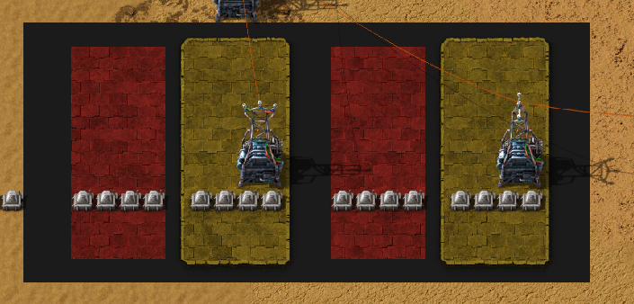
Minimalist Version:
- MinimalistBinViz.png (850.84 KiB) Viewed 5100 times
1 tile spacing between nibble or quadbit and 2 tile spacing between octet or byte
less combinators but still doing the binary operation with carry
One can choose the color of its preference to make nice decoration this is the minimalist version it is delivered without even a packaging !
It does look much better with spacing thank you for your remark
Re: Minimalist signal filtering device
Nice tool. Especially the use of the sign bit as bit detector.
How about less combinators (combinators have more than 1 channel. They can be used simultaneously for every possible real and virtual signal):
How about less combinators (combinators have more than 1 channel. They can be used simultaneously for every possible real and virtual signal):
- Screenshot 2021-12-01 214115.png (870.24 KiB) Viewed 5088 times
Re: Minimalist signal filtering device
That's using less combinators true, but it's doing a bit different thing if one wants to nitpick 
You first turn the number A in its ones complement using a XOR-1 calling it N, then you add 1 to this number calling it T, and then you use the bitshift on all intermediate number A N and T at the same time on parralel channel.
Turning the number negative in decimal first and then displaying it in binary form would be easier and not even require the ones complement but i said it felt like cheating to me !
What you do is a bit different and i didn't know i could do the XOR-1 to get the ones complement so i'm happy i learn something but i don't like the fact that you add 1 to the number before you do the bitshifting because it gets rid of the logic used to take care of the carry which could be used as a base to implement addition/subtraction.
(also it was the thing that took the most time to figure out with minimum combinators me and you just skip it ! x)
Still nice build ! the easiest to use for practical reasons imo
Then i used the other condition for the 2nd row of lamp.
But it was still required to do a logical operation based on the state of the lamp, hence the >= decider in the middle to ouput some 1 (because using the sign bit as detector doesn't yield 0 or 1).
The bottom decider is used to output another 1 or not to make it 2 and turn off the lamp when there is a carry, which is passed onto the bit on the left until there is no carry left which was the most tricky wiring part.
You first turn the number A in its ones complement using a XOR-1 calling it N, then you add 1 to this number calling it T, and then you use the bitshift on all intermediate number A N and T at the same time on parralel channel.
Turning the number negative in decimal first and then displaying it in binary form would be easier and not even require the ones complement but i said it felt like cheating to me !
What you do is a bit different and i didn't know i could do the XOR-1 to get the ones complement so i'm happy i learn something but i don't like the fact that you add 1 to the number before you do the bitshifting because it gets rid of the logic used to take care of the carry which could be used as a base to implement addition/subtraction.
(also it was the thing that took the most time to figure out with minimum combinators me and you just skip it ! x)
Still nice build ! the easiest to use for practical reasons imo
This is the kind of thing i realized when looking at the signals once the bigger machine was made. It's (relatively) easier to spot the pattern and realize the bitshifting to the right was not necessary since all the lit lamp were the lamp receiving negative signal, ( the >>31 was just transforming a large negative number into -1). i just changed the condition of the lamp and removed the combinator.
Then i used the other condition for the 2nd row of lamp.
But it was still required to do a logical operation based on the state of the lamp, hence the >= decider in the middle to ouput some 1 (because using the sign bit as detector doesn't yield 0 or 1).
The bottom decider is used to output another 1 or not to make it 2 and turn off the lamp when there is a carry, which is passed onto the bit on the left until there is no carry left which was the most tricky wiring part
Next challenge : without any combinators ?
[edit:] doesn't seem possible after some discussion, would be way too slow to read big numbers.
Last edited by mmmPI on Thu Dec 02, 2021 9:48 am, edited 2 times in total.
Re: Minimalist signal filtering device
Well, yes, in a way you're right. But not completely. You are first extracting, then processing every bit on its own. You're simulating how a computer will process every single bit. I used the computer to do the operations. I was treating the combinator as processor register and acted as if i'm doing assembly programming the processor. I used the number storage of the combinator similar to a register in a CPU and first performed the negation, then the two's complement by increment. There are assembly language instructions for these operations, and this reminded me of these.mmmPI wrote: ↑Wed Dec 01, 2021 9:58 pmYou first turn the number A in its ones complement using a XOR-1 calling it N, then you add 1 to this number calling it T, and then you use the bitshift on all intermediate number A N and T at the same time on parralel channel.
Turning the number negative in decimal first and then displaying it in binary form would be easier and not even require the ones complement but i said it felt like cheating to me !
You were cheating as well: you didn't invert the number for the one's complement, you just reversed the lamp condition. I, on the other side, actually computed the complement.
If I were utterly cheating, I would have inverted the condition as well, and for the two's complement, I would simply multiply A with -1. But I first built the inverse, then incremented. That is really how the two's complement is created by a basic CPU. Keep in mind the early CPUs didn't have an assembly instruction for multiply. Only add, subtract, increment by 1, decrement by 1, and, or, xor, neg.
Not completely without - it's not possible to identify one bit in a lamp condition alone. You need at least one mathematical operation to filter the bit.
I did this, I spread the bits with an AND operation over the 32 virtual signals 0, 1, 2, ..., 9, A, B,..., V:
And I apologize for utterly cheating this time. I don't compute the complement, I inverted the condition. And for the two's complement, I simply multiplied with -1 to save 1 combinator. The lamp display proves that the combinator arithmetic actually uses the two's complement to represent negative numbers.
But in doing bit manipulation in assembly language, and this is very similar to this, "cheating" is the key to short and fast programs. If there is some magic CPU command that does what I need, irrespective if that CPU command was designed for this or not, I will use that command.
- Screenshot 2021-12-02 050716.png (821.57 KiB) Viewed 5064 times
Re: Minimalist signal filtering device
That's cool ! I was unaware of those things, that's why i enjoy playing Factorio, i play video games all the time, and realised it would be better if those hours spent could teach me some things more useful for general purposes than the name and range of 12427 different magic spells or war vehicules or the perfect map of imaginary places which i already have plenty in mindTertius wrote: ↑Thu Dec 02, 2021 4:11 am[...]first extracting, then processing every bit on its own.[...] simulating how a computer will process every single bit. I used the computer to do the operations. I was treating the combinator as processor register and acted as if i'm doing assembly programming the processor. I used the number storage of the combinator similar to a register in a CPU and first performed the negation, then the two's complement by increment. There are assembly language instructions for these operations, and this reminded me of these.
That is really how the two's complement is created by a basic CPU. Keep in mind the early CPUs didn't have an assembly instruction for multiply. Only add, subtract, increment by 1, decrement by 1, and, or, xor, neg.
Now it give the wikipedia pages about these things more sense to me and it's easier to know what to document on using real life things that factorio simulate. Making it easier to go see more specialized material than wikipedia. thank you
The lamps are like mini NOT gate they do invert the number bit by bit, i've just decided to include that in the rules and there is no rule saying the rules shouldn't change midway
You saved me some time !! i noticed yesterday after posting that all the lamps in the same row used the same condition and thought there must be a way to add some logic to them to avoid using the left bitshift every time with a different value. I fiddle around a bit but couldn't find anything and made it my plan for this morning haha. Instead i just learned from your blueprint.Tertius wrote: ↑Thu Dec 02, 2021 4:11 amit's not possible to identify one bit in a lamp condition alone. You need at least one mathematical operation to filter the bit.
I did this, I spread the bits with an AND operation over the 32 virtual signals 0, 1, 2, ..., 9, A, B,..., V:
I don't compute the complement, I inverted the condition. And for the two's complement, I simply multiplied with -1 to save 1 combinator. The lamp display proves that the combinator arithmetic actually uses the two's complement to represent negative numbers.
Again i think it is (somewhat) easier to understand/have inspiration/observe once the machine is made, looking at yours is inspiring :
You have used a signal filtering device inside the binary visualiser from a certain point of view
In your example each signal is in fact aimed at one particular lamp that has a precise column. In this case filtering the different signals is done to reproduce a number.
Now from what i understand this can be adapted to have pretty similar function as the other signal filtering device you made : The way you create the number present in (i) can be a way to transmit a string of 0 and 1 but they do not have to be interpreted as only 1 number but could instead be triggering many conditions.
Let say you only use the 3 first bits and you make it really simple, you can go for a convention that would mean most significant bit is [Iron ore] then [copper ore] then [coal] would be the least significant, then you create a (i) number whose binary form would be 100 or 010 or 001 depending if you want [iron] or [copper] or [coal] and you send 111 if you need all of them.
The binary visualiser you made is the binary decoder, one would also require an encoder something using 2^x or 1<<x to add bits to the number (i) at the correct place.
The operation (i) AND EACH -> EACH , and having different power of 2 hardcoded in constant combinators on different channels to make the EACH is very elegant (imo) enabling the idea to not feel like a 100 combinator build in my mind.
If you have a train station that is made to provide iron, you only need to read 1 bit so only 1 power of 2 hardocded per ressources in my 3 bit example. And for copper you just change the power of 2 hardcoded in the constant. If the station require iron or copper, it must be able to emit 100 or 110 or 010.
the implementation could require precise management of the timing in case of wire transmission because the number (i) must readapt as soon as quantity is changing ( when the need for [iron] stops ) so it could require pulsing the number (i) at some interval and then storing the 0 and 1 where required. ( this could make it be a 100+ combinator builds though but if it's 5 to 10 per station or so it's ok for my personnal taste)
but you can also imagine with the example of the 3 bit number that you have a train with 3 wagons, or a train that can contain 111 fish or a train loaded with a fish a piece of wood and a car in the first dedicated wagon. ( for wireless transmission but that's no longer using binary operation on circuit number anymore, just hacking the logic ).
I agree with you this is not the kind of cheating where someone unfairly loses, that's not cheating, more like "cheating"
One could try to make a decimal->binary converter without combinator, it sounds like it could be very slow to do the part you describe as extracting the number under its binary form because you could always put 634 645 425 iron plate in some wired chest and count them 1 by 1 with an inserter and add a bit at the correct place everytime you reach a power of 2
Re: Minimalist signal filtering device
Yes, the AND operation I used is a common way to apply a mask to a value. It keeps desired bits and drops undesired bits. You set desired bits to 1 in the mask, and undesired bits to 0. This is so generic, you will find it in every computer algorithm that deals with single bits. I used it for the lamps to just keep the bit the lamp is designated for, then tested for "not zero" as lamp condition.
CPUs often have TEST or BIT instructions that do this in a single operation, they apply the mask or test a single bit. The actual result is discarded, but the ZERO status flag is set for the result, which then can be used for conditional jumps. Unfortunately, Factorio's circuit conditions don't have a bit test operation that applies a given mask to a value and results true for non-zero and false for zero. Probably a bit too esoteric and not low level enough.
This is a way to use every single bit of some value. Unfortunately, you can only transmit the information that ore x is needed, but not how much, since you use only 1 bit for this information. Factorio works a bit different, in my opinion. You can have a value for every ingame material at no computing cost, and additionally the virtual signals. I see a single signal similar to a bit in a CPU register. A Factorio circuit network "register" contains all values for all signals. They are similar in spirit, because all the bits in a CPU register are manipulated simultaneously by an operation, while all the signals from a circuit network are manipulated simultaneously as well by a circuit network operation.mmmPI wrote: ↑Thu Dec 02, 2021 9:45 amLet say you only use the 3 first bits and you make it really simple, you can go for a convention that would mean most significant bit is [Iron ore] then [copper ore] then [coal] would be the least significant, then you create a (i) number whose binary form would be 100 or 010 or 001 depending if you want [iron] or [copper] or [coal] and you send 111 if you need all of them.
8 bits are a byte for a computer, while all signal channels together are a Factorio-byte for Factorio.
So I would not try to stuff information about real items into single bits of the same signal, because they all have their own signal already.
However, you can use virtual signals to provide information about things that don't have their own signal. Wagons for example. If you need to tell which wagon has some property, designate a bit for every wagon, then stuff the bits into some virtual signal. But you can also simply say signal 0 is wagon 0, signal 1 is wagon 1 etc. It's not that you must use single bits. To operate on all signals, you still have the everything, each and anything operators.
I just got an idea. I made a supply train system that designates every material hardcoded to some wagon. You have to carefully balance the static setup to not overfill a wagon. In the constant combinator definitions, all stacks of all materials must not exceed the wagon capacity.
Now there might be a solution by designating the top 2 or 3 bits of an item signal to the wagon number for dynamic allocation, so you can know which item is in which wagon. On the other hand, this information isn't provided if you read the train content at a station. It just outputs what is in the train as a whole, without information about which material is in which wagon. It's possible to recover this information by going through every signal for every wagon and set a filter inserter filter and see if the inserter is able to pull an item from a given wagon. If it gets an item, we have the wagon number with this item. However, this seems way too complex and grossly violates the KISS (keep it simple, stupid) principle.
KISS: If you cannot do something with 3, maximum 4 combinators, it's too complex in my opinion. It's super interesting to develop stuff as in this thread, but for real use in real Factorio factories, it should be small. The best logic is directly in an activation condition, optionally with a single combinator attached. If you need more, check if this is really required or if a different approach is what you really need.
So forget this "idea"
Re: Minimalist signal filtering device
The train example was not the best choice from me because it imply practical application in a place where better alternative exist.Tertius wrote: ↑Thu Dec 02, 2021 12:36 pmThis is a way to use every single bit of some value. Unfortunately, you can only transmit the information that ore x is needed, but not how much, since you use only 1 bit for this information. Factorio works a bit different, in my opinion. You can have a value for every ingame material at no computing cost, and additionally the virtual signals. I see a single signal similar to a bit in a CPU register. A Factorio circuit network "register" contains all values for all signals. They are similar in spirit, because all the bits in a CPU register are manipulated simultaneously by an operation, while all the signals from a circuit network are manipulated simultaneously as well by a circuit network operation.
8 bits are a byte for a computer, while all signal channels together are a Factorio-byte for Factorio.
So I would not try to stuff information about real items into single bits of the same signal, because they all have their own signal already.
However, you can use virtual signals to provide information about things that don't have their own signal. Wagons for example. If you need to tell which wagon has some property, designate a bit for every wagon, then stuff the bits into some virtual signal. But you can also simply say signal 0 is wagon 0, signal 1 is wagon 1 etc. It's not that you must use single bits. To operate on all signals, you still have the everything, each and anything operators.
The balden part i'm not sure what you mean precisely; i understand the general idea that the amout of information transmitted in each tick in factorio through a single wire is much more than the amount of information that goes through a single wire in real life computer. Each "channel" in factorio according to the wiki denomination can have a value of a 32bit number which would correspond to 32 wire just for the amount of information in a single "channel" like channel A or B or C or (i) or [copper ore]. because real life computer logic is at the lowest level applied on electric current that can only have value 1 or 0.
I understand (and agree) that for practical applications like "in real factorio train station" it is easiest to use integer number value and do computation and logic on integer value such as given by the circuit network. And to use 1 channel per item since they are available with some exta (according to the kiss principle).
There are still a few points in relation with the "signal filtering" that i would like to develop
1) about filtering signals and/or filtering value.
The original post is a very generic multiplier doing "a*b" which is described in the wiki in the advanced tutorial section, mostly it seems as a display of the circuits network capabilities. One of the description of the use is a dictionnary/array system. Which to me seems "esoteric" given your previousus of the word
But if you consider one of the value a or b will only have 1 single bit in a channel, it becomes a tool to filter some signal, you multiply some channel by 1 and if not they disappear. Then you don't need such complicated multiplier because you don't need to handle the same range of value for a and b, if you consider b will only be equal to 1 then you can have a full range of value for a which is more than the original contraption.
Another way to do the operation of selecting some channels amongst others could be to use a control signal, in your latest build the signal (i), instead of the full range of all channel as b.
case 1) starting with a range of number for " all channel in a" and a range of number for "all channel in b",
case 2) then having a range of number for " all channel in a" and a value = 1 for "all channel in b"
case 3) then having a "set of preset value for a that encode the channel in "a" and a "control signal that can take a set of value that correspond to channel to select on the other wire" in "b"
Those are different method that correspond to potentially a range of application that overlap. some being clearly over-engineering a solution given what you consider your techical issue which could be one's liking, i could easily relate to that
2) about trains
Considering the 3 different case above and the complexity of one's train network, or willingness to create a very over-engineered routing system there are many different ways to do things. Or to use controlled-train for other purposes than carrying material on rails. You can use the channel [iron ore] to transmit information about [iron ore] and consider that each item will use its own channel.
Inside of 1 channel the numbers will sum up so you need to either transmit the information in sequence over time and use a system of latch.
And/or with bit operations and "signal filtering" you can encode different informations in the same channel which has its virtue too.
Routing trains directly using circuit network is cumberstone compared to not doing it. It could be a fun time spent fiddling though and in this case knowing several ways to do things even some that may seem not practical are like "another string to the bow".
Another way to illustrate the method related to outpost & monitoring quantities instead of routing trains or transmitting information about precise quantity could be to have each outpost assigned one of the 32 bits and have a number broadcasted on a channel based on which bits was activated. If you have more than 32 outpost but less than 64 then you only need 2 tick to transmit how many and which outpost are available, and if you have more than 64 but less than 96 you need 3 ticks to update.
If you consider this over-engineered system, you can update the different [iron] [copper] [circuit] and so on at the same time in parralel.You will need 1 tick per 32 outpost instead of 1 tick per outpost if you were to transmit individually the quantity. Instead of transmitting a quantity you only transmit 1 bit per outpost but you could imagine taking 2 bit per outpost or 4 bit per outpost. The trade off of stuffing information into everysingle bit is with time With 4 bit of information per outpost , in 1 tick there could be 8 outpost of [iron] and [copper] and [circuit] to be updated at the same time.
4 bits could represent 1 2 3 4 as increasing buffered quantity for a lamp display
3) about wireless transmission
I think this is a distinct point than train because here they are meant to be considered as information carrier as much as material carrier. This is also a side point so i will develop it too much since this thread is mostly about signals. The wireless transmission still features encoder and decoder. And is a wireless transmission of signal. The train and the material it contains is supposed to represent the information.
In a theoric example you can make it so that the 2 first wagon of the train are unloaded in their own separate chests array while the next 4 wagon are supposed to receive some material.
First wagon possible content :
1) a fish
2) a piece of wood
3) a car
4) a tank
5) a power switch
6) a stack inserter
7) a heat pipe
8) a distractor capsule
Second wagon possible content :
1) a fish
2) a piece of wood
3) a car
4) a tank
5) a power switch
6) a stack inserter
7) a heat pipe
8) a distractor capsule
You transmit 2 different 8-bit number. (1) could encode the material and the (2) the quantity with increment of 1000 2000 5000 and so on
fish<<7 output A
wood <<6 output A
car <<5 output A
tank << 4 output A
power switch <<3 output A
stack inserter<<2 output A
heat pipe << 1 output A
distractor capsule+0 output A
If A= x output iron [1]
if A = y output copper [1]
if A = z output coal [1]
1 wagon has 40 slot, so you can transmit a full number and 8 extra bit (which i took as example ) enough for to code for every item even with all the mods in the portal i think :p
You can "read content" when the train arrive because it is empty except the wagon where the items to encode the numbers are ONLY if you choose different unique item for the 2 wagon unlike in my previous list. In this case you need to unload the first wagon and the second wagon in different set of chest.
then the logic would want to store those 2 numbers, reload the item that the train brought, fill in the trains with useful material and let it go, and then reset the 2 numbers once train has left.
It's one way to do wireless signal transmission using bitwise operation to reconstruct a binary number to code a channel, and another one to code a number on this channel
4) about the music
What music ? the music you can make in factorio ! and i say you because i cannot do the music myself haha. I have gathered over the time some blueprints from joining random multiplayer server, like a tourist that take pictures of cool thing.
Again disclaimer, this was made by an author i can't credit due to not having the name
music box
In the picture is circled the area to play/reset. Just above are combinators doing mysterious magic very similar to the one you used already.
It does filter signal based on certain value in control channel. Maybe it's not as real factorio as trains but it's still there rather than my imaginary descriptions of potential train system
I used 32 lamp machine to try and understand this music box but the process is not complete

Re: Minimalist signal filtering device
I feel like none of you have heard of the technicalfactorio github yet, so here's a link to a filter circuit that handles all input values.
https://github.com/technicalfactorio/te ... _whitelist
https://github.com/technicalfactorio/te ... _whitelist
Re: Minimalist signal filtering device
Thank you, the circuit is somewhat similar to some in the thread, it's a 6 combinator build that uses bitwise operations. The amount of combinator is nessary to handle all value positive and negative for all signals. It's a bit more generic than the more compact builds, but has a wider range of accepted value for a and b including negative and allowing filtering using negative value too.
I didn't know about the technicalfactorio github. There are other combinators contraptions such as a multiplier "a*b" similar to the original build too (pair wise multiplication ). The distinction is well made between signal filter and multiplier.
I spent a bit of time looking at the music box, little note : using every single bit to encode information is not only used to transmit faster, but can also be used to compress some builds. Time or space efficiency. The later being visible in the music box, the music is stored in constant combinators. From what i understand this is a clock accessing memory.
The signal filter/multiplier seem to be used for what the wiki describe as array/dictonnary same as the multiplier that was shown. When the clock increment, it sometimes reaches a value that correspond to some musical note. In this case one of the constant has its value sent to the area where bitwise operation occurs. There are up to 5 different moment that correspond to a note playing in 1 constant combinators. Those are the value encoded in channel 0 1 2 3 4.
Then each of those moment can trigger 5 different speakers with a precise pitch which is a numerical value. Those are the value encoded in channel A B C D E
Now if you want to play [note1] on speaker A at time 0, but [note2] on speaker A at time 1, you need 2 different pitch value for [note1] and [note2]. But both need to be stored in the channel A of the same constant combinator.
This is why a signal filter using bitshifting operation is used. The value encoded in the channel A in 1 constant combinator is possibly storing up to 5 different number, [note1][note2][note3][note4][note5]. this looks like a very big number like 900M in the circuit, but it should be understood as something like : 25 12 16 25 25 in decimal. The 32 bit string is cut into small pieces by the different mask represented by the black/gray channel. and 25 is a value that makes a pleasing sound to the ear in the music, but i can't tell which particular note.
The clock count up to a number that makes it read all the notes in all constant combinator, and then reset for another tune.
I really like the relation between the binary numbers and the music
I didn't know about the technicalfactorio github. There are other combinators contraptions such as a multiplier "a*b" similar to the original build too (pair wise multiplication ). The distinction is well made between signal filter and multiplier.
I spent a bit of time looking at the music box, little note : using every single bit to encode information is not only used to transmit faster, but can also be used to compress some builds. Time or space efficiency. The later being visible in the music box, the music is stored in constant combinators. From what i understand this is a clock accessing memory.
The signal filter/multiplier seem to be used for what the wiki describe as array/dictonnary same as the multiplier that was shown. When the clock increment, it sometimes reaches a value that correspond to some musical note. In this case one of the constant has its value sent to the area where bitwise operation occurs. There are up to 5 different moment that correspond to a note playing in 1 constant combinators. Those are the value encoded in channel 0 1 2 3 4.
Then each of those moment can trigger 5 different speakers with a precise pitch which is a numerical value. Those are the value encoded in channel A B C D E
Now if you want to play [note1] on speaker A at time 0, but [note2] on speaker A at time 1, you need 2 different pitch value for [note1] and [note2]. But both need to be stored in the channel A of the same constant combinator.
This is why a signal filter using bitshifting operation is used. The value encoded in the channel A in 1 constant combinator is possibly storing up to 5 different number, [note1][note2][note3][note4][note5]. this looks like a very big number like 900M in the circuit, but it should be understood as something like : 25 12 16 25 25 in decimal. The 32 bit string is cut into small pieces by the different mask represented by the black/gray channel. and 25 is a value that makes a pleasing sound to the ear in the music, but i can't tell which particular note
The clock count up to a number that makes it read all the notes in all constant combinator, and then reset for another tune.
I really like the relation between the binary numbers and the music
-
SteelWolf300

- Inserter

- Posts: 30
- Joined: Sat Apr 09, 2016 11:21 am
- Contact:
Re: Minimalist signal filtering device
Hi all, I built this array filter, I wanted to share it!
It can filter any signal based on if it is present (or missing) in the mask. This works over all possible values (no overflow).
The idea behind it is that adding 2^31 makes any positive number negative and vice versa, and adding it twice gets back to the original number.
I had to tweak it a bit, but at the end, it filters correctly any signal (I have tested it even for special values like 2^31-1 and -2^31).
Instructions (also in blueprint description):
An other version of this that use one less tick to update the outputs on mask change (but the values -2^31 and -2^31+1 are hardcoded in this one, if factorio switches signal type to 64bits integers, it would need to be adapted. In the previous blueprint, I found this weired trick using bit shift: 1<<-1 == -2^31; this works by shifting 1 to the right by (-1 modulo 32), i.e. by 31 bits).
Also, here is my benchmark, to make sure the filter works as intended:
EDIT: Thanks to this post, I learned about the technicalfactorio solution (whitelist and blacklist produce the exact same outputs)... Yes their version use less combinators, and the mask is handled in two ticks only, but I am still proud of my version, because I came up with this by myself, and you cannot take this away from me
It can filter any signal based on if it is present (or missing) in the mask. This works over all possible values (no overflow).
The idea behind it is that adding 2^31 makes any positive number negative and vice versa, and adding it twice gets back to the original number.
I had to tweak it a bit, but at the end, it filters correctly any signal (I have tested it even for special values like 2^31-1 and -2^31).
- Array filter signals.png (360.47 KiB) Viewed 4389 times
- Array filter legend.png (248.78 KiB) Viewed 4389 times
Pointwise array filtering:
OUT1 = IN1 if MASK != 0
OUT2 = IN2 if MASK == 0
Combine IN1 and IN2 to make a signal splitter.
Combine OUT1 and OUT2 to make an IF-THEN-ELSE gate.
(IN*)->(OUT*): 2 ticks delay.
(MASK)->(OUT*): 5 ticks delay (4 if already 0|1 signal).
Signal architecture agnostic (32bits/64bits/any bits); overflow proof.
-- by SteelWolf300 --
An other version of this that use one less tick to update the outputs on mask change (but the values -2^31 and -2^31+1 are hardcoded in this one, if factorio switches signal type to 64bits integers, it would need to be adapted. In the previous blueprint, I found this weired trick using bit shift: 1<<-1 == -2^31; this works by shifting 1 to the right by (-1 modulo 32), i.e. by 31 bits).
Also, here is my benchmark, to make sure the filter works as intended:
EDIT: Thanks to this post, I learned about the technicalfactorio solution (whitelist and blacklist produce the exact same outputs)... Yes their version use less combinators, and the mask is handled in two ticks only, but I am still proud of my version, because I came up with this by myself, and you cannot take this away from me
Re: Minimalist signal filtering device
Thank you for sharing your build. I have a blueprint book for those and yours will definitly fit in there waiting for that time when it is properly examinedSteelWolf300 wrote: ↑Wed Mar 02, 2022 8:08 amHi all, I built this array filter, I wanted to share it!
EDIT: Thanks to this post, I learned about the technicalfactorio solution (whitelist and blacklist produce the exact same outputs)... Yes their version use less combinators, and the mask is handled in two ticks only, but I am still proud of my version, because I came up with this by myself, and you cannot take this away from me
Also it's easier to remember stuff when you come up with it yourself, i think , so i specifically agree with you on the second part of the EDIT.