
I've been experimenting with tankless nuclear reactor design and wondering if there's a way to simultaneously get the benefits of a tankless/pumpless design (minimal power use, reduced footprint, reduced fluidboxes) and the benefit of a tank-ed design to control fuel insertion.
And I think I've worked out a monitoring system that uses an absolutely tiny amount of stuff, and can control any given number of nuclear installations (with each installation being capable of having thousands of individual reactors within it).
The fundamental basis of it is that all turbines, given adequate steam, will consume it at the same rate. Therefore, if you have a reliable measure of how much steam one turbine consumes, you know how much every turbine is consuming.
Measuring this requires one tank, and two pumps. Either boiler->pump->tank->pump->2x steam engine or heat exchanger -> pump -> tank -> pump -> turbine will work, but note that if you're using boiler steam you have to use steam engines and not a turbine, because turbines on boiler steam have (functionally) a higher priority than turbines on nuclear steam.
The pumps are configured to supply steam into the tank if it's less than some threshold (I usually set 1000) and to remove it from the tank if it is at or above that threshold. This way the tank is only ever doing one thing at a time, draining or filling. Because a turbine's maximum draw is 1 steam/tick, and a pump going entity->tank is ~200/tick (slowing as the tank fills), the vast majority of the tank's time is spent in drain mode. The tank is wired to a negative-edge detection, which outputs the differential between the tank's current value and its value on the last tick, so long as that's less than zero.
That's the instrumentation. It functionally is measuring the steam consumption of any given steam-powered turbine or steam engine on that particular grid.
To turn it into a useful reactor control, a bit more math is needed. You need to work out how much steam a given turbine will use in order to consume an entire fuel cell cycle, which in turn depends on the number of reactors and turbines. The formula for this, for a 2xN layout, is 12000 steam * 160 MW * (# of reactors - 1) / (5.8 MW * # of turbines). The 12000 steam comes from the number of ticks in a cycle (12000) and the amount of steam a turbine consumes at full draw (1 steam/tick).
The constants, once combined, work out to ~331,034.5, which limits the number of reactors this piece of it can control to around 6000. Past that, you'd need to sacrifice precision, or use more bignum circuitry, or build a second reactor.
In any case, 331034 * (# of reactors - 1) / # of turbines is the amount of steam required to fully extract (or almost so, anyway) the entire energy of a fuel cell. The outputs from the pilot turbine measurements are summed in a memory cell and, as they're all negative, summed against that value. Once it drops below zero, the prior fuel cell has been fully consumed, which means it is time to insert a new one. At that point -- provided a standard clock mechanism also agrees --, the memory cell resets, to prevent error accumulations, and the cycle restarts.
Q: What if there isn't enough steam to drive the main turbines?
A: The steam-consumed measurement will be higher than the actual steam consumed, meaning that the total energy contained in the system will climb. Either that will solve the steam issue, or the reactor design has throughput issues you need to fix.
Q: What if the pilot turbine/steam engine doesn't have enough steam?
A: You need to figure out why your fuel delivery or pump power broke.
Q: Why use this instead of just measuring a tank?
A: A few reasons. Aside from likely saving on fluid boxes, particularly for very large systems, this setup is as far as I can figure the earliest possible way to detect a complete fuel cell consumption, and therefore the one that makes for the most responsive system. In particular, setups that rely on measuring steam tanks are vulnerable to a demand shock: If draw is low, most of the heat in the reactors and heat pipes will be consumed before the heat exchangers stop keeping up. If draw then spikes up to full load, it can take quite a while before all the exchangers are once again producing, potentially leading to unexpected brownouts. This system, while still rationing cells, will keep the potential for 100% exchanger operation at a moment's notice.
Q: Where's the blueprints???
A:
Steam flow meter:
Threshold calculator & memory cell:
Using one turbine to control an arbitrarily large number of nuclear reactors

Re: Using one turbine to control an arbitrarily large number of nuclear reactors
Very clever, I'm definitely going to use this trick.
I have a few notes about it I'd like to share.
edit: Updated the bp so that if the reactor was starved for a long time, the controller won't flood the reactors with fuel cells. Changed the formula in the bp description to include a 0.5% safety margin.
edit 2: Added extra logic to adjustably increase fuel consumption at low power usage to compensate for energy lost due to too small of an energy buffer, preventing periodic black-outs. Input is the percentage of the energy produced in one fuel cycle that can be buffered. From what I can tell, any descent reactor design will inevitably be able to buffer at least 60% of a fuel cycle. Now it can safely be used to improve the fuel efficiency of reactors that weren't designed to be fuel efficient!
Reactor Pilot Controller
I have a few notes about it I'd like to share.
- Your blueprints don't include the actual mechanism for resetting the memory cell.
- I don't see why the flow meter and memory cell shouldn't already be connected in a single blueprint.
- During the time when the reactor input inserters should be enabled, up to and including the one tick when the memory cell is being reset, the steam flow measurements are discarded. This error actually accumulates as a slow loss of maximum total heat in the reactors, until there's not enough heat to supply all of the turbines between fuel cell insertions, power production decreases due to lack of steam, and, like you said, the measured flow becomes too large, creating a net positive accumulation of total heat until steam production catches up.
- Steam turbines actually produce 5.82 MW of power according to the wiki, the game just doesn't display the third digit. Using 5.8 MW in the formula gives a result that's too high, which also causes periodic brown-outs like the previous point. Here's the corrected formula assuming a 2xN reactor setup:
Code: Select all
329,896 * (# of reactors - 1) / (# of turbines) = Steam to be consumed by the pilot turbine before inserting another fuel cell. - Pumps have an output buffer that gets forced out even if the pump is disabled. During one tick when switching from filling to emptying, steam is pumped out of the tank while steam from the buffer of the disabled pump is also being pumped in, so the measured flow is too small, again leading to periodic brown-outs.
- Despite fixing all of the above problems, my 4 reactor / 82 turbine test setup was still showing periodic dips of ~150kW... until it suddenly wasn't, and I have no idea why. So I'm just going to blame floating point error and advise you to subtract a few points from the result of the formula since it's better for it to be too low than too high.
- Most reactor designs try to be as close to the ideal ratio of turbines to reactors as possible, so aside from extreme(ly impractical) edge cases, the result of the formula will always be around 12,000. It'll be slightly below 12,000 if there are too many turbines, and slightly above if there are too few, so you could just calculate the formula outside the game and keep the result in a constant combinator. That way this trick can control any number of reactors, not just 6,000.
edit: Updated the bp so that if the reactor was starved for a long time, the controller won't flood the reactors with fuel cells. Changed the formula in the bp description to include a 0.5% safety margin.
edit 2: Added extra logic to adjustably increase fuel consumption at low power usage to compensate for energy lost due to too small of an energy buffer, preventing periodic black-outs. Input is the percentage of the energy produced in one fuel cycle that can be buffered. From what I can tell, any descent reactor design will inevitably be able to buffer at least 60% of a fuel cycle. Now it can safely be used to improve the fuel efficiency of reactors that weren't designed to be fuel efficient!
Reactor Pilot Controller
Last edited by farcast on Mon Aug 24, 2020 11:15 pm, edited 2 times in total.
Efficient inefficient design.
-
burninghey
- Fast Inserter

- Posts: 115
- Joined: Fri Sep 14, 2018 2:06 am
- Contact:
Re: Using one turbine to control an arbitrarily large number of nuclear reactors
Very nice. So this little electronics could control all the reactors at the map?
Re: Using one turbine to control an arbitrarily large number of nuclear reactors
That's right! As long as they all have the same design, one controller is all you need. If you use a mix of different designs (eg. a 4x reactor and an 8x reactor, or a 4x with 80 turbines and a 4x with 82), then you need a separate controller for each design.
After some more testing, it seems a reactor still needs to be able to buffer an entire fuel cycle of energy in some form (heat, steam, accumulators) to completely avoid demand shock. Since we don't need to read from tanks anymore, this can be done entirely with heat pipes that have a higher energy storage density than steam tanks (exact numbers can be found on the wiki). It's also easier to share heat with all of the turbines than it is to share steam. Keep in mind that the steam in the pipes and turbines, and the heat in heat exchangers and reactors all count towards the energy buffer.
edit: So what I thought was demand shock was actually black-outs caused by low power usage & too small of an energy buffer. Energy was lost when the reactor temperature maxed out, the circuit didn't account for that, so it waited too long before inserting another fuel cell, causing periodic black-outs. It's not a problem if the reactor has a big enough buffer, but I wanted to be able to use any reactor with this controller. I've updated my blueprint with a way to compensate for any lost energy.
Efficient inefficient design.
Re: Using one turbine to control an arbitrarily large number of nuclear reactors
All of these stem from the same root cause: My intent was to have a separate memory cell for any given reactor, and my reactor controls are designed to generate a one-tick wide pulse, which I use as the reset indicator for both its own internal timing and for the memory cell posted here. There is a discard during the reset signal, and it would be possible, if you wanted exact precision, to cache the incoming signal while the primary cell is being reset, but as it is one tick out of a minimum of 12,000, I considered that error acceptable.farcast wrote: ↑Fri Aug 21, 2020 8:05 amVery clever, I'm definitely going to use this trick.
I have a few notes about it I'd like to share.
- Your blueprints don't include the actual mechanism for resetting the memory cell.
- I don't see why the flow meter and memory cell shouldn't already be connected in a single blueprint.
- During the time when the reactor input inserters should be enabled, up to and including the one tick when the memory cell is being reset, the steam flow measurements are discarded. This error actually accumulates as a slow loss of maximum total heat in the reactors, until there's not enough heat to supply all of the turbines between fuel cell insertions, power production decreases due to lack of steam, and, like you said, the measured flow becomes too large, creating a net positive accumulation of total heat until steam production catches up.
My reactor controls are set up so that all conditions must be go in order to insert fuel. This is typically an explicit timer, a manual override, and something saying cells are needed: tank measurements, accumulator measurements, this power cell setup, or whatever. You can see an example of it here: viewtopic.php?f=208&t=87432. Because of the explicit timer, I don't have the issue with fuel cell flood you discussed; if a reactor hasn't completed its cycle, nothing happens.
What was your fix for the pump buffer being dumped? I can see some ways the error might be reduced -- extending the range of operation, so the pump toggles less frequently, for example -- but if there's a more exact solution I'm all ears. Good point on the power formula though.
- Steam turbines actually produce 5.82 MW of power according to the wiki, the game just doesn't display the third digit. Using 5.8 MW in the formula gives a result that's too high, which also causes periodic brown-outs like the previous point. Here's the corrected formula assuming a 2xN reactor setup:
Code: Select all
329,896 * (# of reactors - 1) / (# of turbines) = Steam to be consumed by the pilot turbine before inserting another fuel cell.- Pumps have an output buffer that gets forced out even if the pump is disabled. During one tick when switching from filling to emptying, steam is pumped out of the tank while steam from the buffer of the disabled pump is also being pumped in, so the measured flow is too small, again leading to periodic brown-outs.
- Despite fixing all of the above problems, my 4 reactor / 82 turbine test setup was still showing periodic dips of ~150kW... until it suddenly wasn't, and I have no idea why. So I'm just going to blame floating point error and advise you to subtract a few points from the result of the formula since it's better for it to be too low than too high.
Yeah, could do that. The idea was that you'd just plop down your reactors of whatever size and plug in the numbers assuming a 2xN, but expanding nuclear reactors isn't that common a task so it might just be better to, as you say, reconfigure a constant combinator by hand every now and then.
- Most reactor designs try to be as close to the ideal ratio of turbines to reactors as possible, so aside from extreme(ly impractical) edge cases, the result of the formula will always be around 12,000. It'll be slightly below 12,000 if there are too many turbines, and slightly above if there are too few, so you could just calculate the formula outside the game and keep the result in a constant combinator. That way this trick can control any number of reactors, not just 6,000.
Thanks for your comments!
Re: Using one turbine to control an arbitrarily large number of nuclear reactors
I added a one tick pause in the transition from filling to emptying, where both pumps are disabled. I did this by adding a decider with a seemingly unnecessary condition where the combinator delay is what I actually use, since I couldn't find a way to add this delay without adding another combinator. One tick seems to be enough time for the buffer to empty out completely. At least, I haven't had any problems with it so far.
Interesting note, I noticed that this buffer won't empty out completely if the connected fluid box is filled past a certain point. The arbitrary choice of switching pumps at 1000 fluid is low enough to avoid this being a problem, luckily enough.
Efficient inefficient design.
Re: Using one turbine to control an arbitrarily large number of nuclear reactors
That's handy. The choice of fluid size wasn't arbitrary, though; I needed inflow to the tank to be as fast as possible (to reduce the number of times it needs to toggle back and forth) but with enough capacity to allow the measurement system to not be bottlenecked. I knew from prior work with fluid flow measurement that as a tank fills, the measured inflow from a pump actually drops below the nominal amount, even when directly connected as here. While it doesn't become substantial until significantly higher fluid levels, there wasn't an real reason to go higher up. Similarly, the flow out declines as the fluid level drops. Fortunately, the required throughput there is far less that on the input side.
In fact, the limit could probably be shoved significantly lower down. Could be worth experimenting with.
Re: Using one turbine to control an arbitrarily large number of nuclear reactors
Ok, did some work on the measurement side of things; it's no longer quite so slapdash:
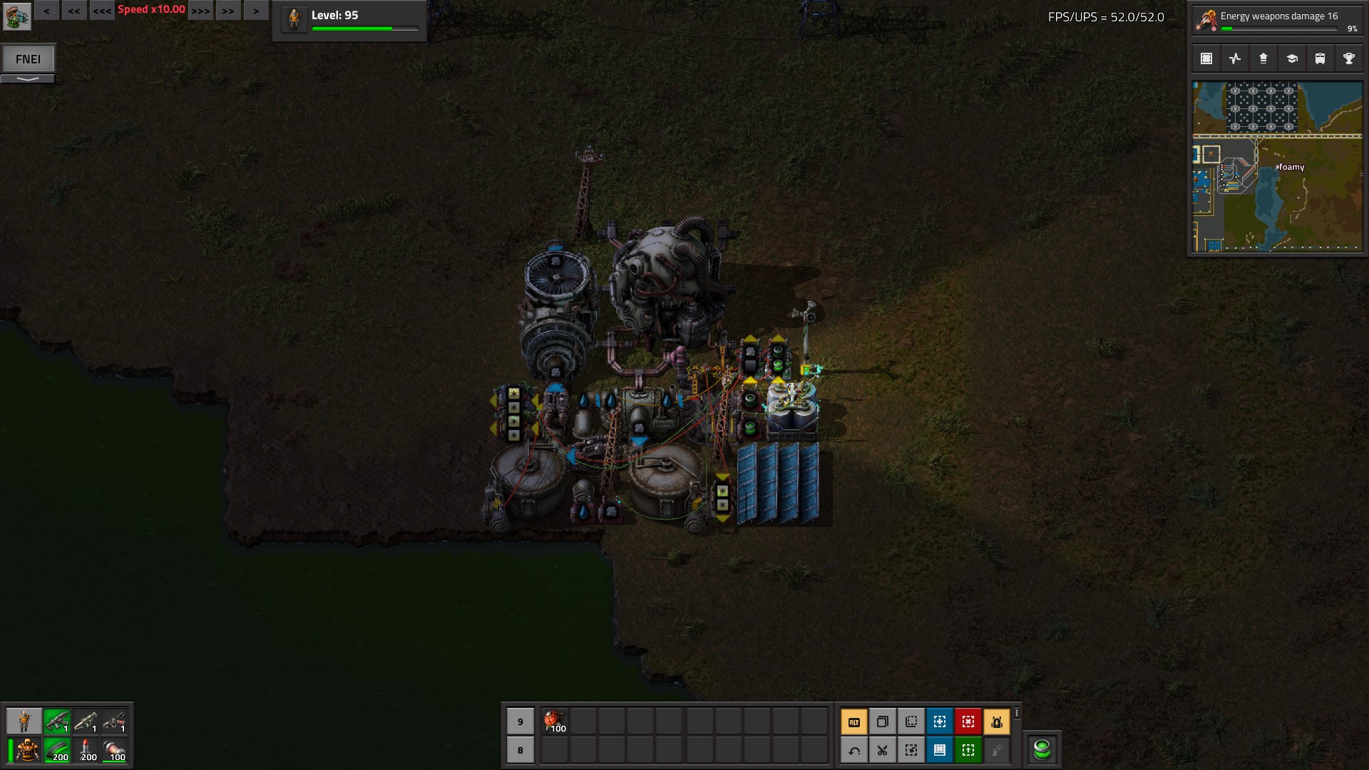
Now incorporates a direct UPS in the form of a solar panel and accumulator for the pumps, reactor inserters, and combinators, which does not touch the steam turbine; a reactor with independent controls and fuel feed/removal; a buffer steam tank to ensure there's always lots available for the measuring station; a reconfiguration into a square instead of a line; the addition of a one-tick pause between either the input pump or the output pump stopping and the other starting; and a power pole directly next to the turbine for connection to the grid it is measuring.
This system generates negative pulses, each one of which can be regarded as representing one tick of full turbine generation. For using this to control any given reactor design, all you need to know is the output of the reactors, and the output of the steam turbines. The number of ticks of full turbine output before the reactor needs refueling is the reactor output, times 12000, divided by the turbine output. Thus you can capture the negative pulses in a memory cell and use them to count down from that number. When the total hits 0, you need more fuel.
EDIT: Because of the minimum delay of an inserter swing, 26 ticks for a fast-tier inserter operating chest-to-reactor, it is advisable to add a small safety margin here to avoid gradually losing heat.
If you have multiple reactor complexes, regardless of if they have the same design or not, you don't need an additional measuring station -- just an additional memory cells & target numbers.
Re: Using one turbine to control an arbitrarily large number of nuclear reactors
Something else you can do with this system: Circuit-driven tracking of the actual percentage of your steam generation you're using/not using.
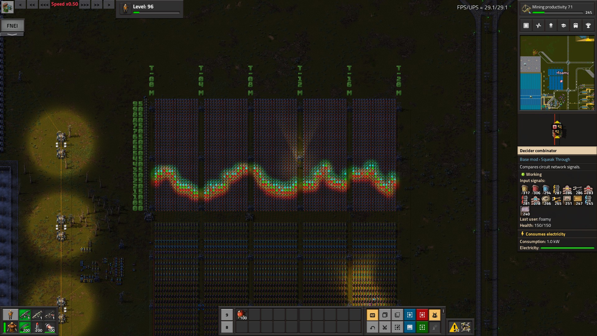
In this case, I charted remaining capacity. It's time to expand my reactor :v
In this case, I charted remaining capacity. It's time to expand my reactor :v
Re: Using one turbine to control an arbitrarily large number of nuclear reactors
Cleaned up the display a bit; here it is post plant expansion:
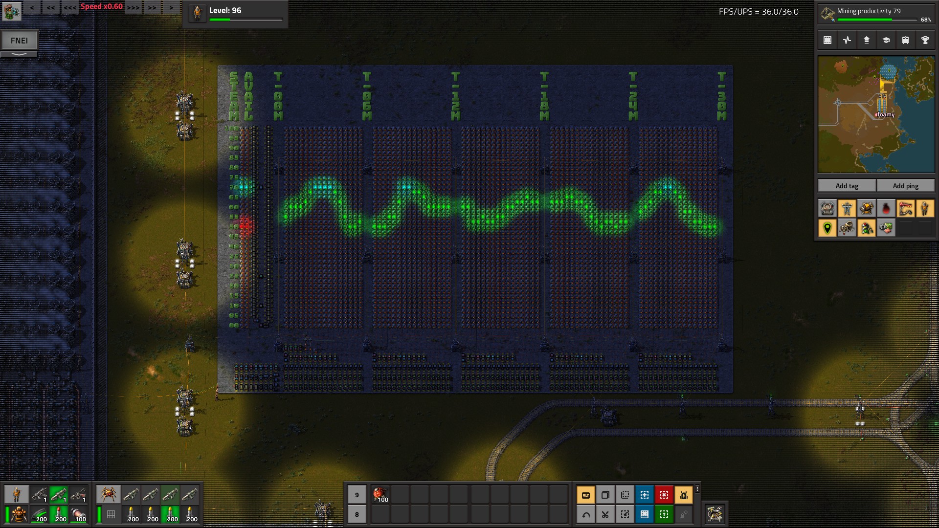
@farcast: The microbrownouts you described I encountered briefly at the start, but after I added a very small fudge factor to the 'time to insert cells' trigger -- about a 1% safety margin, which means energy gradually accumulates in the system until the excess is lost due to insufficient buffer, which I think is largely acceptable -- that problem went away. System has been happily controlling a substantial nuclear plant for dozens of hours now without issue. In the last 10 hours, consumption of fuel cells has averaged 9.7/m, and steam turbine power production has averaged 5.1 GW. Each cell represents, in the current reactor configuration, ~31.6GJ, so if you run the math you get 5.1GW of fuel cells producing 5.1GW of steam power, which is about 40% the actual sustained generation capacity of the 84 reactors.
So, it looks like that both ta. my reactor layout buffers properly and b. that the gauge does work very effectively as a control system to avoid fuel cell wastage.
Re: Using one turbine to control an arbitrarily large number of nuclear reactors
@foamy: The errors from the problems I listed are indeed small enough that a small fudge factor is enough to deal with them, I just think it's more satisfying to solve the root of the problem.
The blackouts I mentioned in my edit caused by too small of an energy buffer only occur at low power consumption. As for how low is low, that depends on the percentage of energy of one fuel cycle that can't be buffered. For example, a reactor that can buffer 80% of a fuel cycle won't have any blackouts until less than 20% of the max sustainable power output is being used during each fuel cycle. I think I didn't even consider heat pipes when calculating the inevitable 60% energy buffer, or at least not as many as would actually be necessary, so a typical reactor would probably have closer to an 80% buffer. Running your reactor at 40% capacity is probably too high to reproduce this issue. Even if it's a bit unrealistic to assume a reactor is only running at ~10% capacity, I think it can happen while the factory is under construction without researching anything.
Calculating, or even measuring, the actual buffer size a reactor has is really annoying, which is why I'm only mentioning rough percentages.
Efficient inefficient design.
Re: Using one turbine to control an arbitrarily large number of nuclear reactors
Ah, I see the issue: An unexamined and unstated assumption on my part, which is, specifically, that there is enough buffer capacity to last an entire cycle. If not, then use of it as a controller will be off because while the measurements will accurately track how much energy is removed from the system, to better than 99% precision, they cannot account for energy that was never created in the first place (because of buffer overflow).
At least, not directly. However, if you have a reactor of known buffer capacity and known generation capacity, you can use this to track how much energy was removed specifically during the period of active generation, and from there calculate whether or not there was in fact buffer overflow and use that to adjust when the next cycle should trigger. The circuitry for that's a bit more complicated, but not impossible.
I simply didn't think of it because the reactor designs I use are buffered -- by heat pipes, hence why I wanted to design this in the first place --, so that isn't a source of energy loss. Thus by adding very slightly more than's needed, it tends to a steady state where buffer loss equates to the very slight extra power being added.
One of the interesting things about running this long term in a real game, though, is that I realized I'd over-estimated how much buffer I had.
This is the reactor:
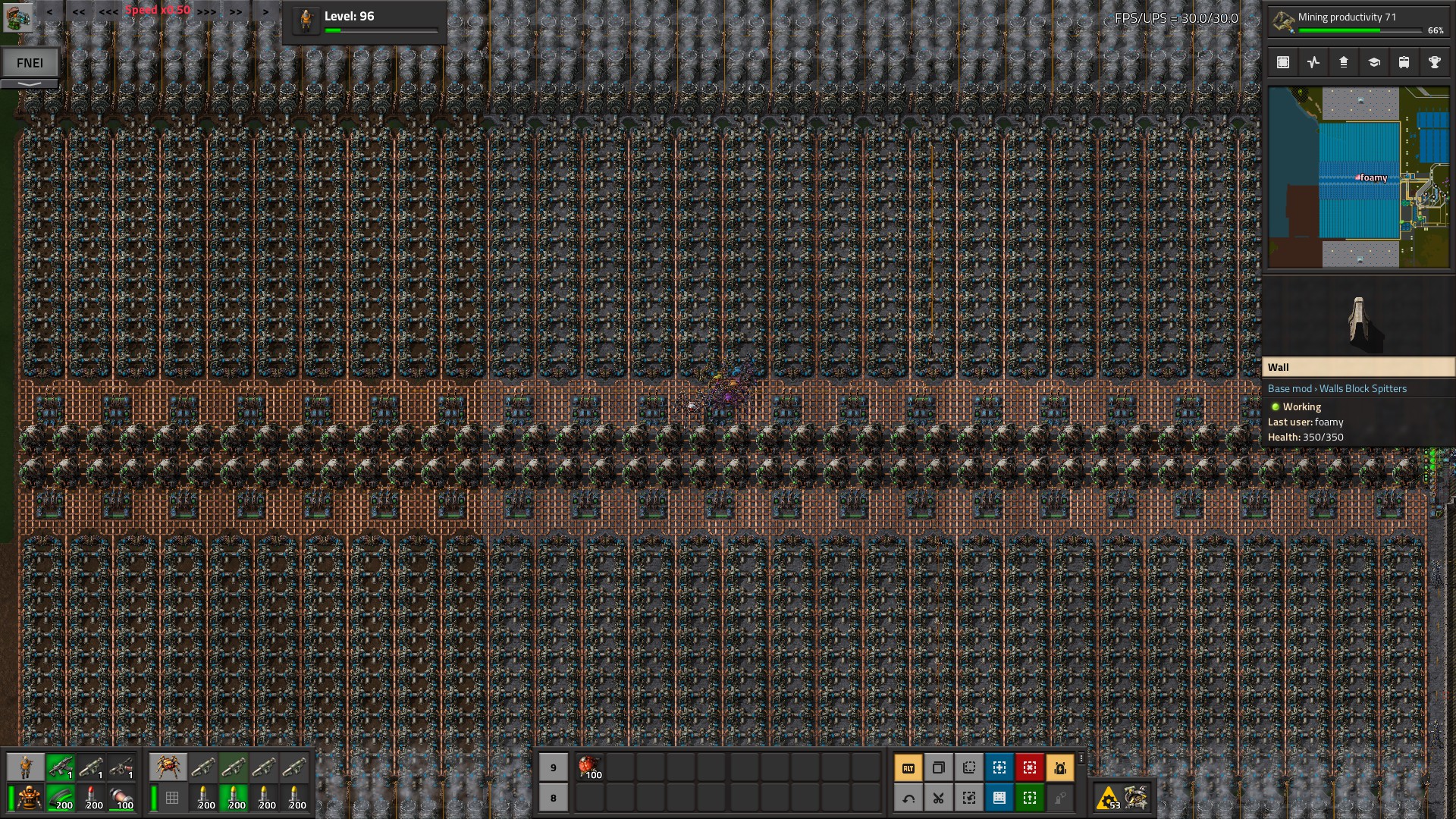
I had calculated the buffer based on the full 500C range, and it has approximately 55.3 heat pipes per reactor (there's 40 heat pipes every 6 tiles in the heat exchanger rows, plus 22 for each reactor to connect to them). At 500MJ per, plus 5GJ for reactor, that'd be just a hair over 32GJ, plus whatever steam is in the system. So from a cold start it can completely buffer a full cycle with no draw.
But that's not how a reactor generally operates and the controller never lets it get that cool. Which is good, because it means the controller's working correctly, but it also means I have noticeably less buffer space than I had imagined if the reactor were to transition to a null load-scenario. While I haven't tested this as yet, because I don't want to disconnect my factory's power source, I think that if it were to go to a null load from a working one (immediately prior to the next fuel insertion), the pipes and reactor would level out at around 600-650C. That means the buffer only has 70-80% of the capacity I had originally planned on.
Still, for a working reactor design, that's plenty. I might go design those compensation circuits, though, just to be sure.
At least, not directly. However, if you have a reactor of known buffer capacity and known generation capacity, you can use this to track how much energy was removed specifically during the period of active generation, and from there calculate whether or not there was in fact buffer overflow and use that to adjust when the next cycle should trigger. The circuitry for that's a bit more complicated, but not impossible.
I simply didn't think of it because the reactor designs I use are buffered -- by heat pipes, hence why I wanted to design this in the first place --, so that isn't a source of energy loss. Thus by adding very slightly more than's needed, it tends to a steady state where buffer loss equates to the very slight extra power being added.
One of the interesting things about running this long term in a real game, though, is that I realized I'd over-estimated how much buffer I had.
This is the reactor:
I had calculated the buffer based on the full 500C range, and it has approximately 55.3 heat pipes per reactor (there's 40 heat pipes every 6 tiles in the heat exchanger rows, plus 22 for each reactor to connect to them). At 500MJ per, plus 5GJ for reactor, that'd be just a hair over 32GJ, plus whatever steam is in the system. So from a cold start it can completely buffer a full cycle with no draw.
But that's not how a reactor generally operates and the controller never lets it get that cool. Which is good, because it means the controller's working correctly, but it also means I have noticeably less buffer space than I had imagined if the reactor were to transition to a null load-scenario. While I haven't tested this as yet, because I don't want to disconnect my factory's power source, I think that if it were to go to a null load from a working one (immediately prior to the next fuel insertion), the pipes and reactor would level out at around 600-650C. That means the buffer only has 70-80% of the capacity I had originally planned on.
Still, for a working reactor design, that's plenty. I might go design those compensation circuits, though, just to be sure.
Re: Using one turbine to control an arbitrarily large number of nuclear reactors
I was wrong about reactors inevitably being able to buffer 60% of a fuel cycle... sort of.
In my solution for compensating lost energy, I assumed a reactor would have a known buffer size. At the end of a fuel cycle, the reactor could have at most that much energy stored. The steam count in memory is like a count of how much energy is left in the system, so I added logic to limit the max steam value at the end of a fuel cycle to what the reactor can buffer. To get what that max value should be, I added a setting for what percent of energy of one fuel cycle can be buffered, and used that percent of the steam setting.
The trouble with this came from looking for a reliable way of finding what the percentage setting should be for a given reactor design. It seemed like I got different results depending on how I tested for it, but I think I know what's going on now. To transfer a given amount of energy as heat, there needs to be a proportional(I think) difference in temperature. This leads to a portion of the energy capacity being dedicated to supporting the full power output. If any of that heat gets used, then part of the fuel cycle is spent replacing it. Additionally, the reactor can reach max temp before all of the energy capacity has been used. Some energy is lost, but more energy is still being stored, just at a slower rate.
Here's a very precise graph of a reactor running at full power to show what I mean:
The heat pipes are alongside exchangers. After every exchanger, the temperature curve gets less steep as less power needs to be transferred. The entire curve moves up as the lossless storage is filled, and moves down when energy is being used at full power. When the reactor temp maxes out, the lossy storage is filled, and the fill rate slows down as the temperature curve flattens out. Energy is lost if the peak of the curve hits 1000 degrees, and brownouts occur if the lowest point reaches 500 degrees.
If the lossy storage is included when calculating the buffer size of a reactor, then my solution fails if there's zero demand at the start of a fuel cycle, then 100% demand just after a reactor reaches max temp. Some energy was lost, yet the buffer wasn't filled. Lossy storage can't be included for my solution to work, and the bad news is that this can be a huge portion of the total energy capacity. If the heat pipes are long enough, then all of the energy capacity can be lossy storage.
The good news is that it's somewhat easy to find the lossless heat storage of a reactor: Run the reactor at full power demand until the temperature stabilizes. By full power I mean the power output of the reactors, not the turbines. Find the exchanger with the lowest temperature, and the reactor with the highest temperature. Subtract 500°C from the lowest temperature to get the temperature range for lossless storage below the curve. Subtract the highest temperature from 1000°C to get the range for lossless storage above the curve. Add them together to get the temperature range for all lossless storage. Multiply that by the number of heat pipes. Each exchanger counts as one heat pipe, and each reactor counts as 10 heat pipes since they have 10 times the heat capacity. With a heat capacity of 1MJ/°C, the result is how many megajoules can be stored as heat and refilled at full power. Divide that by how many megajoules are produced in one fuel cycle, multiply by 100, and you've got the percentage of a fuel cycle that can be stored as heat.
In short, the whole formula is:
From there, you just need to find how much energy gets stored as steam, though that's probably not so simple either.
I have ignored the minimum 1°C difference rule in this explanation, but I don't think that significantly effects the formula, or the conclusions I made.
In my solution for compensating lost energy, I assumed a reactor would have a known buffer size. At the end of a fuel cycle, the reactor could have at most that much energy stored. The steam count in memory is like a count of how much energy is left in the system, so I added logic to limit the max steam value at the end of a fuel cycle to what the reactor can buffer. To get what that max value should be, I added a setting for what percent of energy of one fuel cycle can be buffered, and used that percent of the steam setting.
The trouble with this came from looking for a reliable way of finding what the percentage setting should be for a given reactor design. It seemed like I got different results depending on how I tested for it, but I think I know what's going on now. To transfer a given amount of energy as heat, there needs to be a proportional(I think) difference in temperature. This leads to a portion of the energy capacity being dedicated to supporting the full power output. If any of that heat gets used, then part of the fuel cycle is spent replacing it. Additionally, the reactor can reach max temp before all of the energy capacity has been used. Some energy is lost, but more energy is still being stored, just at a slower rate.
Here's a very precise graph of a reactor running at full power to show what I mean:
- Reactor heat graph.png (12.28 KiB) Viewed 5687 times
If the lossy storage is included when calculating the buffer size of a reactor, then my solution fails if there's zero demand at the start of a fuel cycle, then 100% demand just after a reactor reaches max temp. Some energy was lost, yet the buffer wasn't filled. Lossy storage can't be included for my solution to work, and the bad news is that this can be a huge portion of the total energy capacity. If the heat pipes are long enough, then all of the energy capacity can be lossy storage.
The good news is that it's somewhat easy to find the lossless heat storage of a reactor: Run the reactor at full power demand until the temperature stabilizes. By full power I mean the power output of the reactors, not the turbines. Find the exchanger with the lowest temperature, and the reactor with the highest temperature. Subtract 500°C from the lowest temperature to get the temperature range for lossless storage below the curve. Subtract the highest temperature from 1000°C to get the range for lossless storage above the curve. Add them together to get the temperature range for all lossless storage. Multiply that by the number of heat pipes. Each exchanger counts as one heat pipe, and each reactor counts as 10 heat pipes since they have 10 times the heat capacity. With a heat capacity of 1MJ/°C, the result is how many megajoules can be stored as heat and refilled at full power. Divide that by how many megajoules are produced in one fuel cycle, multiply by 100, and you've got the percentage of a fuel cycle that can be stored as heat.
In short, the whole formula is:
Code: Select all
((500°C + lowest exchanger temperature - highest reactor temperature)
* (#of heat pipes + #of exchangers + 10*#of reactors)
* (1 MJ/°C))
* 100
/ (Total megawatt output of reactors * 200 seconds)
= Percent of one fuel cycle that can be stored as heat without losing energy.I have ignored the minimum 1°C difference rule in this explanation, but I don't think that significantly effects the formula, or the conclusions I made.
Efficient inefficient design.
Re: Using one turbine to control an arbitrarily large number of nuclear reactors
I found a way to control the pumps without needing an extra combinator. Disabling the output pump if the steam level changes at all will have it active every other tick. If the steam level drops to the level that enables the input pump, then in the next tick the output will be disabled while the input is enabled. The input will change the steam level, keeping the output disabled, and the steam level will continue to change as the pump buffer empties out. The output condition can be achieved by connecting the pump to the tank and the arithmetic combinator used for the edge detector.
Combining the new flow meter with my reactor control circuit, and after many attempts at rearranging everything, here is the result.
You technically only need one flow meter for the whole map, so I re-wired my circuit to make it possible for multiple control circuits with different settings to share the same flow meter. That strip of combinators on the side is the entire control circuit, so just make a copy of that and connect it to the decider by the lamp in the same way.
Speaking of the lamp, it blinks whenever the steam level drops. Past 30 steam per second, or roughly half of your maximum power output, it stays on except for when the tank is being refilled. It's like a little activity light for your power grid.
Also by the lamp is a pair of constant combinators that lets you manually enable the fuel rod inserters. Just copy both of them, rotate, and paste to turn it on, then rotate and paste again to turn it off. Use this to bring newly built reactors up to max temperature to fill the supporting heat I mentioned earlier.
I changed the formula in the bp description to have a 0.2% safety margin since I felt 0.5% was too much and I can't make up my mind.
I added extra combinators to isolate the wire for the fuel inserters from the ever changing memory values, since that's good for UPS or something.
Something I realized recently is that even if a reactor has a small energy buffer, using this circuit will still greatly reduce the number of fuel rods consumed at low power demand compared to burning fuel rods all the time. For example, if the buffer size setting is 30% and power demand averages at 20%, then fuel efficiency will be at 50% (20% consumed, 30% stored, 50% lost at max temp or overcompensating). Twice as many fuel rods will be consumed than needed, but that's equivalent to 40% power demand at 100% efficiency, which results in 60% fewer fuel rods being consumed compared to burning all the time.
Next on the To Do list is making an automated system for finding what the buffer setting should be for a particular reactor, since no amount of math can beat rigorous testing. Honestly, why didn't I think of this sooner?
edit: Ah hah! By adding a second lamp, the full range of steam consumption can be visualized by blinking lights! Truly perfection.
Pilot Reactor:
Combining the new flow meter with my reactor control circuit, and after many attempts at rearranging everything, here is the result.
- Pilot Reactor.png (422.37 KiB) Viewed 5559 times
Speaking of the lamp, it blinks whenever the steam level drops. Past 30 steam per second, or roughly half of your maximum power output, it stays on except for when the tank is being refilled. It's like a little activity light for your power grid.
Also by the lamp is a pair of constant combinators that lets you manually enable the fuel rod inserters. Just copy both of them, rotate, and paste to turn it on, then rotate and paste again to turn it off. Use this to bring newly built reactors up to max temperature to fill the supporting heat I mentioned earlier.
I changed the formula in the bp description to have a 0.2% safety margin since I felt 0.5% was too much and I can't make up my mind.
I added extra combinators to isolate the wire for the fuel inserters from the ever changing memory values, since that's good for UPS or something.
Something I realized recently is that even if a reactor has a small energy buffer, using this circuit will still greatly reduce the number of fuel rods consumed at low power demand compared to burning fuel rods all the time. For example, if the buffer size setting is 30% and power demand averages at 20%, then fuel efficiency will be at 50% (20% consumed, 30% stored, 50% lost at max temp or overcompensating). Twice as many fuel rods will be consumed than needed, but that's equivalent to 40% power demand at 100% efficiency, which results in 60% fewer fuel rods being consumed compared to burning all the time.
Next on the To Do list is making an automated system for finding what the buffer setting should be for a particular reactor, since no amount of math can beat rigorous testing. Honestly, why didn't I think of this sooner?
edit: Ah hah! By adding a second lamp, the full range of steam consumption can be visualized by blinking lights! Truly perfection.
Pilot Reactor:
Efficient inefficient design.
Re: Using one turbine to control an arbitrarily large number of nuclear reactors
That actually wouldn't have fixed the problem, which is the circuit not knowing that the system would always have a minimum amount of energy, even if that amount is 0. The reactor would still end up burning fuel rods all the time until the steam value in memory catches up. Granted, this was only a problem because my circuit resets the memory cell with the steam setting plus the current value in memory. Now it won't use that result if it's still negative, so it will always reset to 0 at minimum.
Efficient inefficient design.
Re: Using one turbine to control an arbitrarily large number of nuclear reactors
Here it is, an automated system for finding the lossless buffer size of a reactor. It works by simulating what I've found so far to be the worst case scenario, and detecting brownouts. It needs the editor extensions mod for the adjustable power sink with higher priority than accumulators. Running this test in real time would take hours, so I've provided the test as a separate save file to be able to increase the game speed as much as possible.
The worst case scenario is for power demand to be 0% for a percentage of a fuel cycle, then 100% demand the rest of the time, repeated for multiple cycles, until it suddenly stays at 100% demand for multiple cycles. If the percent lossless buffer is greater than or equal to the percentage of the cycle where demand was 0%, then nothing bad will happen. If not, then there will be a brown-out/black-out due to lost energy. This test repeatedly simulates this worst case scenario at different percentages of time where demand is 0%. It starts at 100% of a cycle, then moves down or up depending on if there was or wasn't a brown-out respectively, in steps that halve in size after each test starting at 50% to a minimum of 1%. It should eventually alternate between two percentages, with the lower percentage being directly usable as the buffer size setting for the reactor.
Setup:
- Set steam value. For energy losses to be as easy to detect as possible, the steam setting should be the result of the original formula with no safety margin.
- Build the reactor and use infinity chests to supply it with fuel cells.
- Copy the settings of the burner inserter for the fuel cell inserters, and connect them all with green wire.
- Set the consumption of the infinity accumulators on the right to sum up to exactly as much power as the reactor can sustain.
- Make sure there are no other power consumers on the main power network such as roboports, inserters, or pumps.
- Choose test settings. Signal 1 is for the number of cycles in the first stage of each test. Signal 2 is for the number of cycles in the second stage of each test. It should be fine to leave these settings at their defaults of 4 and 2 respectively.
- Reset the test to start a new round of testing.
- Attachments
-
- Reactor Buffer Test.zip
- (1.89 MiB) Downloaded 530 times
Efficient inefficient design.