¡¿Fluid Mechanics?!

Don't know how to use a machine? Looking for efficient setups? Stuck in a mission?
Post Reply
Camalie
Burner Inserter
Burner Inserter
Posts: 8
Joined: Thu Apr 28, 2016 1:00 pm
Contact:

¡¿Fluid Mechanics?!

Post by Camalie »

Hi, I was toying with the idea of creating a tool to help me math out pipes and pumping setups for liquid throughput and liquid "latency" (like how fast will the system equalize given an input flow/output drain), but I don't understand the fluid mechanics well enough in this game to math stuff out. Could I get some pointers as to how it actually works, technically? What I am looking for is basically some pseudo-code sketch for how the fluid boxes are updated with each tick in Factorio.

Let's say there's three fluid boxes: L, M, and R. L is on the left, R is on the right, M is in the middle, and they are all connected. Their build order is from right to left, so R was placed before M, and L last. (I understand that build order somehow affects the fluid update step, that fluidboxes do not get calculated simultaneously but rather serially?) They're all empty and in default state. L is size 10, M is size 20, and R is size 30 (base_area 1, 2, and 3 respectively).

Now, 10 units of a fluid with flow_to_energy_ratio=0.59 and pressure_to_speed_ratio=0.4 (the defaults) is put into L in a single tick. Can someone walk me through what actually gets calculated in the following ticks? I tried printing lots of values where I measure fluidboxes in a sort of minimod but all it did was confuse me some more.

I have tried to research this on the forums, but the best I could find was viewtopic.php?p=143780#p143780 who doesn't know, exactly. And viewtopic.php?p=125742#p125742 who says he DID figure out the math but then doesn't actually post it, just some graphs as far as I can see... The wiki's "Pipe Physics" page is woefully short on actual physics.

Storage tanks seem easy, something like this:

Code: Select all

// update flow based on previous flow & pressure difference
// (why is base_area given in 10 liquid units?)
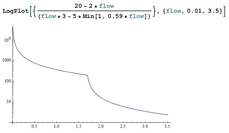
flow = flow*fluid.flow_to_energy_ratio + fluid.pressure_to_speed_ratio*(A.amount/A.base_area - B.amount/B.base_area)
A.amount -= flow
B.amount += flow
between storage tanks A and B. That seems to simulate storage tank mechanics as far as I have been able to measure.

But with pipes it's different(?!). There's some extra factor(s) here I can't account for. I can't figure out why their flow is so high and then how it "breaks" in edge cases, with different build orders or around a corner. I can have a line of pipes, "magically pumped full" with 10 units every tick in one end, drained completely in the other, and the liquid will end up "equalizing" on totally different values depending on the order I set it up and it all just hurts my brain trying to "reverse engineer" it.

XKnight
Filter Inserter
Filter Inserter
Posts: 329
Joined: Thu May 28, 2015 10:40 pm
Contact:

Re: ¡¿Fluid Mechanics?!

Post by XKnight »

If you have some questions regarding fluid mechanics you can always ask them in dedicated topic viewtopic.php?f=18&t=19851.
As for me, I didn't post the actual math because everyone is interested only in conclusions and applications.
The answer on your question is:
Pressure = current water in entity / max water in entity
Flow from A to B = 10 * (Pressure A - Pressure B) * 0.4 + "Flow on the previous tick * 0.59" limited with -1...1


Example: let's say we want to calculate max distance which can maintain specific Flow.
Because this system is stable, flow between each 2 pipe segments is constant.
Flow from i to i+1 = Flow from 0 to 1 = Flow.
Let's say string was built according to flow direction.
"Flow from i to i+1" = 10 * (("water in i" + "amount of water transfered from previous segment") /10 - "water in i+1" / 10) * 0.4 + Min[Flow * 0.59, 1]
Flow = 10 * ("water diff" / 10 + Flow /10) * 0.4 + Min[Flow * 0.59, 1]
Flow * 0.6 = "water diff" *0.4 + Min[Flow * 0.59, 1]
"water diff" = (Flow * 0.6 - Min[Flow * 0.59, 1]) / 0.4
Max distance = "water amount in first segment" / "water diff" = (10 - Flow) / ( (Flow * 0.6 - Min[Flow * 0.59, 1]) / 0.4)
Max distance = (20 - 2 Flow) / (3 Flow - 5 * Min[Flow*0.59, 1])
Plot

Aru
Fast Inserter
Fast Inserter
Posts: 212
Joined: Wed Apr 13, 2016 11:31 pm
Contact:

Re: ¡¿Fluid Mechanics?!

Post by Aru »

I am extremely interested in the mechanics, how else can I properly simulate them and derive useful formulas as you just did? Thank you for figuring this out. How on Earth did you figure out that the momentum component alone is capped to [-1,1], and only for containers other than storage tanks?

In case anyone else is wondering, "pressure" means ratio of current amount to maximum in the container. And, every fluid intake, and every fluid output, corresponds to an internal container. Small pumps have an internal container, so do offshore pumps, and input/output slots of chemical plants, refineries, assemblers (set to electric engine or fluid barrels), and of course pipe segments. All of these containers have maximum of 10, so 5 fluid is 5/10 = 0.5 "pressure". With the exception of storage tank, where 1250/2500 = 0.5 "pressure". And, the calculations are done on a per-joint basis. Everywhere two containers connect is a joint. There is a list of joints maintained inside the game, and they are in the same order that the joints are created, with newest joints at the end. The calculations are done one at a time in order, and they're re-done 60 times per second (once per game engine update, presumably this number is chosen to match 60 Hz monitors). The flow rates are each applied after being calculated, which is why the order matters. If all flows were calculated before being applied it would not matter, but that's not how it's done. The formulas that are derived above take this oddity into account. The "flow" they work with is flow per tick - 1/60th of a second.

Post Reply

Return to “Gameplay Help”